Driver TS Parameters: Re (DC Resistance) & Le (Voice Coil Inductance)
Re is the DC resistance of the loudspeaker’s voice coil, you should not confuse this with impedance, although related, the two are different.
Measuring the resistance of a speaker with a multi-meter, the reading you get across the terminals should be close to the manufacturer’s specified Re, it’s not unusual to get a minor variation from manufacturer’s published specifications, chances are the Voice Coil resistance will actually be correct and your multi-meter is what’s wrong.
So why is Re around 5-6 ohms, but the impedance specified as 8 ohms. Let’s look at what Re actually signifies, it’s the DC resistance of the wire in the voice coil. If you were to unwind your voice coil, and run it out in a straight line, connect it to a battery or other power source you could predict the current through the wire using ohm’s law: V = IR, and this resistance would be an accurate measure of how much the wire resists the flow of DC electrical current through it.
All good so far, but when you wind copper into a voice coil, you create an inductor. An inductor will still behave like a straight wire when it comes to DC, (Direct Current) however, inductors behave differently when subjected to AC (Alternating current) signals. The output from your amplifier is an AC signal, as it alternates in polarity and varies in amplitude. Inductors resist change in current, when you apply an AC signal to an inductor it will create a back EMF to try to resist the change of current, creating additional ‘reactance’, when you add the reactance to the resistance, you get the driver’s impedance. If you want a simple analogy for an inductor, you could compare it to the suspension of a car, putting weight in a car will make the shock absorbers compress a little, they resist the change, but then remain static doing nothing this would be like applying a DC signal to an inductor, it resists the initial flow of DC current, but once current is flowing the inductor does nothing. If you then drive over lots of bumps, the suspension works by creating a force that pushes back to resist all the little bumps, preventing the force of the bumps reaching the car body, in much the same way that an inductor blocks high frequency signals by creating a back EMF.
One thing to note, is that the reactive component from the voice coil can vary significantly, up to 200 ohms in extreme cases, there is a peak around the drivers resonant frequency, and then there is a increase at the upper end of the driver’s operating range. Typical impedance plot of a bass speaker:
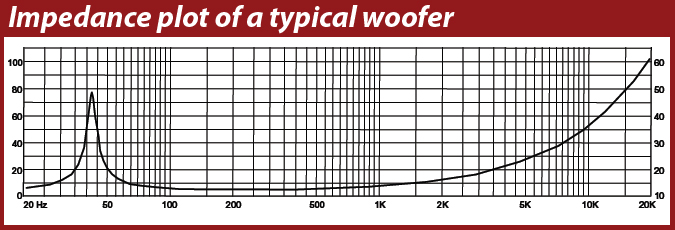
The rising impedance from 1 kHz upwards is caused by the loudspeaker’s inductance. You can see from the above impedance curve that an amplifier will see a higher impedance of nearly 25 ohms at 5 kHz, which would significantly reduce the power that can be delivered to the speaker at those frequencies. To get better high frequency response, the inductance needs to be kept as low as possible by adjusting the voice coil geometry. In some cases this is not possible, so to improve high frequency response a common feature is to include a copper shorting ring in the pole piece of the speaker, this creates a short circuit for induced back EMF, reducing the impedance at higher frequencies and extending the mid-range response. You wont find copper shorting rings in drivers designed for sub-bass or bass applications, as it’s not needed, and they are most often found in higher quality drivers designed for better, smoother high frequency response. Used correctly, the shorting ring can extend higher frequency response by a few kHz.
In the above graph there is also a large peak just above 40Hz, this corresponds to the driver’s resonant frequency. The resonant frequency is the point that the driver will naturally move the most, where the compliance of the suspension and spider for the given moving mass are most susceptible to oscillate. The peak in impedance is caused by the back-emf of the moving coil. The more the cone moves, the greater the back-emf. Since the cone moves most at the resonant frequency, this is where the back-emf will be greatest. An impedance of 40 ohms or more will significantly reduce the power delivered to the speaker by the amplifier at those frequencies, but at the same time the speaker will naturally want to move more easily at the resonant frequency, requiring a little less power to achieve a given excursion. You’ll notice also that the mid-band frequencies show a relatively flat response in impedance, this is where the excursion of the speaker is low, and the impedance will most closely match the ‘nominal impedance’ of 8 ohms.
The 8 ohm rating given to loudspeakers is the average impedance across the drivers main operating range. It’s useful for approximate power calculations and simpler designs, however for more advanced designs it is often desirable to measure the exact impedance at particular frequencies so that variations can be compensated for at the design stage.
Re is used in conjunction with Le (inductance) for purposes of simulating driver performance.
Monday, August 28th 2017 at 01:45 |
[…] Driver TS Parameters: Re (DC Resistance) & Le (Voice Coil Inductance)2nd order Butterworth Passive Crossover Calculator » […]
Tuesday, February 18th 2025 at 01:02 |
[…] Le – Voice Coil Inductance > read more […]