We’re still updating and improving these pages, they are intended as general guidelines to help with the understanding of T&S Parameters and their relevance to speaker design. In some cases, a simplified explanation or example is used to illustrate a point, and may not be 100% accurate in all circumstances.,
BL – Motor Strength or Force Factor > read more
BL (force factor) represents the strength of the magnetic motor system in a loudspeaker. It is calculated as the product of magnetic flux density (B) and length of wire in the magnetic field (L), measured in Tesla meters (T·m). A higher BL indicates a stronger motor, which generally improves control over the cone.
Mms – Moving Mass > read more
Mms refers to the total mass of all moving components of the driver, including the cone, voice coil, dust cap, and the air load around the diaphragm. A higher Mms generally results in a lower resonant frequency (Fs), which can help extend bass response, but it also requires more energy to move. Conversely, a lower Mms allows for better transient response, making it ideal for midrange drivers.
Cms – Compliance of the Driver Suspension > read more
Cms represents the compliance of a speaker’s suspension system, essentially measuring its flexibility. It’s the inverse of stiffness; a higher Cms indicates a more pliable suspension, allowing the cone to move more freely. This flexibility affects the driver’s resonant frequency (Fs); a more compliant suspension results in a lower Fs, enabling better low-frequency reproduction.
Rms – Mechanical Resistance of the Suspension > read more
Rms denotes the mechanical resistance within the driver’s suspension, quantifying the inherent damping due to the materials and construction of components like the surround and spider. Higher Rms values indicate greater energy loss, which can dampen cone movement and affect the driver’s transient response. Balancing Rms is crucial for achieving desired sound characteristics, as excessive mechanical resistance can lead to reduced efficiency and dynamic range.
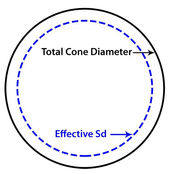
Sd – Effective Diaphragm Area > read more
Sd refers to the effective surface area of the driver’s diaphragm (cone) that actively moves air. It’s typically measured in square meters (m²). A larger Sd allows the driver to displace more air, contributing to higher sound pressure levels, especially at low frequencies. Accurately determining Sd involves measuring the cone’s diameter and accounting for the surround’s contribution to the moving area.
η₀ (Eta Zero) – Reference Efficiency > read more
η₀ represents the efficiency of the driver, given as a percentage, showing how well it converts electrical power into acoustic output. A higher η₀ means the driver is more efficient and produces more SPL for the same input power. Efficiency is closely related to BL, Sd, and Mms, with high-efficiency drivers typically having a strong motor (high BL) and lightweight moving parts (low Mms).
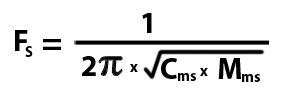
Fs – Free Air Resonance > read more
Fs is the frequency at which the driver naturally resonates when not mounted in an enclosure. It is determined by the moving mass (Mms) and compliance (Cms) of the driver. Lower Fs values indicate better suitability for subwoofers, while higher Fs values are typical for midrange and tweeters, where tight cone control is needed.
Z – Nominal Impedance > read more
Z is the nominal impedance of the driver, typically 4Ω, 8Ω, or 16Ω, and represents the average electrical resistance presented to an amplifier. While Re (DC resistance) is slightly lower, the impedance of a driver varies across different frequencies due to Le (voice coil inductance) and resonance effects.
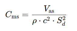
Vas – Equivalent Compliance Volume > read more
Vas represents the volume of air that exhibits the same compliance as the driver’s suspension. Measured in liters, it provides insight into how the driver interacts with the air in an enclosure. A larger Vas suggests a more compliant suspension, often necessitating a larger enclosure for optimal performance. Understanding Vas aids in designing speaker cabinets that complement the driver’s mechanical properties.
Pe – Power Handling Capacity > read more
Pe indicates the thermal power handling capacity of the driver, measured in watts. It defines the maximum continuous power the driver can handle without incurring thermal damage to components like the voice coil. Exceeding Pe can lead to overheating and potential failure. It’s essential to match the amplifier’s output with the driver’s Pe to ensure reliability and longevity.
Xmax – Maximum Linear Excursion > read more
Xmax defines the maximum distance the driver’s cone can move linearly in one direction without significant distortion. Measured in millimeters, it reflects the limits of the voice coil’s travel within the magnetic gap. Exceeding Xmax can cause nonlinear behavior, leading to distortion and potential mechanical damage. Designing with an appropriate Xmax ensures the driver can handle desired sound pressure levels without compromising sound quality.
Xlim – Maximum Physical Excursion Before Damage > read more
Xlim, also known as Xmech or Xdamage, specifies the absolute maximum excursion the driver can endure before mechanical failure occurs. Surpassing Xlim can result in physical damage to components such as the voice coil, spider, or surround. It’s crucial to ensure that the driver operates within safe excursion limits, especially in high-power applications, to maintain durability and performance.
Le – Voice Coil Inductance > read more
Le measures the inductance of the voice coil, typically in millihenries (mH). This parameter affects the driver’s impedance at higher frequencies, influencing the crossover design and overall frequency response. A higher Le can lead to a roll-off in the high-frequency response, making it essential to consider in the design of midrange and high-frequency drivers.
Re – DC Resistance of the Voice Coil > read more
Re denotes the direct current (DC) resistance of the voice coil, measured in ohms (Ω). It’s a fundamental parameter that influences the driver’s electrical damping (Qes) and overall impedance. Accurate knowledge of Re is vital for matching the driver with the amplifier and designing appropriate crossover networks.
Qes – Electrical Quality Factor > read more
Qes represents the electrical damping of the driver at its resonant frequency (Fs). It reflects how the driver’s electrical characteristics control its resonance. A lower Qes indicates higher electrical damping, leading to tighter control over cone movement, which is desirable in achieving accurate sound reproduction.
Qms – Mechanical Quality Factor > read more
Qms quantifies the mechanical damping of the driver, considering losses in the suspension system. It indicates how the mechanical properties influence the driver’s resonance. A higher Qms suggests lower mechanical losses, resulting in a more resonant system. Balancing Qms with Qes is essential for achieving the desired total damping (Qts) and overall sound quality.
Qts – Total Quality Factor > read more
Qts is the combined quality factor that accounts for both electrical (Qes) and mechanical (Qms) damping. It provides a comprehensive understanding of the driver’s damping characteristics at resonance. The value of Qts influences enclosure design decisions:
- Low Qts (< 0.3): Suitable for horn-loaded enclosures, offering tight, controlled bass.
- Medium Qts (0.3 – 0.5): Ideal for bass reflex (ported) enclosures, balancing efficiency and bass
Vd – Peak Displacement Volume > read more
Vd is the product of the effective diaphragm area (Sd) and the maximum linear excursion (Xmax). It quantifies the maximum volume of air the driver can displace, directly influencing its ability to produce low-frequency sound. A higher Vd indicates greater potential for bass output, making it a useful parameter when selecting a suitable woofer.
EBP – Efficiency Bandwidth Product > read more
EBP (Efficiency Bandwidth Product) is a quick way to estimate whether a driver is better suited for a sealed or ported enclosure, calculated as Fs / Qes. A low EBP (< 50) suggests the driver works best in sealed enclosures, while a high EBP (> 100) indicates it is more suitable for ported or horn-loaded designs. While useful as a guideline, EBP isn’t an absolute rule—other factors like Vas, Xmax, and BL also influence enclosure choice.