Loudspeaker Driver Parameters Archive

Qms represents the mechanical damping of a speaker driver, determined by the losses in the suspension system (spider & surround). It indicates how well the driver’s mechanical components control cone movement at resonant frequency (Fs).

What Qms Tells Us About a Driver

  • High Qms (> 5) → Low mechanical losses, meaning the cone moves more freely with minimal damping from the suspension.
  • Low Qms (< 3) → Higher mechanical losses, where the suspension provides more damping and absorbs energy.

How Qms Affects Speaker Design

Qms works alongside Qes (electrical damping) to determine the total damping (Qts) of a driver.

A high Qms driver has minimal mechanical resistance, allowing for greater resonance, but relies more on electrical damping (Qes) for control. A low Qms driver has more built-in damping from the suspension, reducing unwanted resonance but also limiting efficiency.

While Qms alone doesn’t dictate enclosure suitability, it plays a role in how much influence the motor vs. suspension has on cone movement, helping in overall system tuning.

If you’re comparing drivers in detail, it will help to understand some of the more intricate TS Parameters, as over time it will help you differentiate between different drivers and identify which applications they are more suited for.

For example, for a high power 18″ horn loaded bass bin, you will probably be looking for a driver with a high BL, and a strong, rigid cone. A strong cone will generally also be a heavier cone, so you’ll be looking for a driver with a heavier cone. Lightweight cones have been used in horn loaded bass bins, but usually for lower powered applications focusing on upper bass .

For a 12″ midrange driver focused on vocal reproduction, a lighter cone (lower Mms) improves transient response and accuracy.

Mmd is the mass of the moving parts of the driver;  the diaphragm, dust dome and voice coil. The diaphragm is the paper cone in a standard speaker. The voice coil includes the former and the copper wire.  Most definitions online for Mmd seem to just be copies of each other, citing that the surround and spider are included in the moving mass. A bit of further research has suggested that only part of the mass of the spider and surround should be included, as the outside edge of the surround, and the outside edge of the spider are both glued to the chassis, and therefore DO NOT MOVE.

Mms is commonly used in loudspeaker modelling software. It is Mmd plus the ‘air load’. The air load is the air just in front, and just behind the speaker cone that will tend to move back and forth with the cone. It’s just a few grams of air, but for mathematical modelling of speaker performance, needs to be added in. A larger cone will have a larger air load.

Mms is used to calculate other important TS Parameters, such as Qes and Qms which can not be measured directly.

There is one final significant point with regard to the Mms, and that is the relationship to Fs  (Free Air resonance). Mms directly affects Fs (free-air resonance). A heavier cone lowers Fs, while a lighter cone raises it. Fs is also influenced by Cms, the compliance of the suspension. The formula which connects Fs to Mms is as follows:

Fs_Formula

Click here to read more about Thiele Small Parameters: Fs (Free Air Resonance)

As with all Thiele-Small parameters, Mms interacts with other factors like BL, Cms, and cone stiffness. The fact that cone weight, voice coil geometry, magnet strength, cone stiffness all interact and affect each other in both positive and negative ways means that any speaker design always has some compromises. Some might call this optimisation – a driver specifically designed for the best sub-bass response will sacrifice mid and upper bass response.

Lower bass frequencies require a heavier, stiffer cone. However, increasing Mms reduces efficiency, which must be countered with a stronger magnet and a longer voice coil to maintain performance.. Its unsurprising that in many instances, a compromise is settled on, which balances efficiency, resonant frequency, and cost.

For better midrange response, reducing Mms improves accuracy but raises Fs. This works well for midrange drivers but is undesirable for mid-bass woofers. As with most things in life, you can’t have your cake and eat it too. The only way to effectively cover the full frequency range is to use different drivers optimized for specific tasks

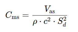
Cms is a measure of the suspension compliance. Compliance is the opposite of stiffness. A driver with a stiff cone suspension will have a low Cms, and a driver with a ‘loose’ cone suspension will have a higher Cms.

Vas is known as the compliance equivalent volume, and is specified in litres. Cms is proportional to Vas, a higher Cms will mean a higher Vas, but what does the Vas figure actually represent?

You could think of the stiffness of the suspension as providing a restoring force that brings the cone back to it’s central ‘neutral’ position. If you were to gently push the dust dome of a driver with your fingertips, one with a stiff suspension would push back harder than one with a loose suspension.

Imagine a situation where you have an imaginary driver  mounted in a sealed box, with an infinitely compliant suspension – ie a suspension that offers no resistance whatsoever to movement. If you were to push the driver cone back into the box, the cone moving back into the box would compress the air inside the box slightly, and when you release the driver cone, the air would push back to restore the cone to its original position. In a box with a small volume, the air would compress more, pushing back harder. As the box size increases, the same distance of movement of the cone will compress the air inside the box less, resulting in a smaller restoring force to push the cone back to it’s original position.

The Vas measurement in litres is the size of the ‘imaginary’ box described above, which has exactly the same restoring force as the suspension of the driver. Cms and Vas are effectively two different ways of describing exactly the same thing, the main reason for converting Cms to Vas is that Vas fits into a lot of formulae better, and allows easier modelling of driver performance.

Air temperature, air pressure and humidity can have a significant effect on Vas measurements, and it is quite common for variations of up to +/- 20% from published specifications. This is a combination of differences of measurement environment, and manufacturing tolerances.

Vas can be used for determining optimum box size for sealed speaker boxes (ie. NOT vented).

If your sealed box is too small, the when the driver cone moves backwards into the box, compressing the air inside the box, the restoring force will be higher than optimal, causing the driver to move back out a little too quickly and potentially gain too much speed, and overshoot, causing it to go further out of the box than it should do. On the return journey, the rarefaction of the air inside the box will pull the cone in too fast, potentially causing it to go in too far. This is known as underdamping, when the movement of the cone gets exaggerated and increased instead of being controlled. This is undesirable as it causes distortion, and potentially affects the cooling of the voice coil

If your sealed box is too big, the air inside the box will will slow the driver from returning to it’s central rest position rather than help it, this can make the box overdamped. Many people consider being slightly overdamped as the best option, as it gives a more accurate sound, but it will often reduce the output volume.

For Bass speakers, critical damping, or ‘perfect’ damping is often what is sought after, this gives the best compromise, where the air inside the box helps restore the driver to it’s natural position, but not too much, and not too little, but just right. A speaker box with a Q of 0.707 is generally regarded as perfectly damped, you could think of this as the Goldilocks Q, where it’s ‘just right’.

The ratio of Vas to box volume = (Qtc/Qts)2 – 1 : 1

Qtc is the desired Q of the speaker, let’s assume we are aiming for a Qtc of 0.7

Qts is the total Q of the driver, available from the manufacturer’s specification sheet. For purposes of some simple maths, let’s use an imaginary driver with a Qts of 0.35.

0.7/0.35 = 2 and 2 squared=4

So our formula gives:(4-1):1 or 3:1

If Vas for our imaginary driver was 180 litres, we would make our box 60 litres to achieve a Qtc of 0.7

Its not unusual to see boxes with a Qtc of up to 1.1, higher Qtc of around 1 is slightly underdamped and will cause a peak in bass response around the resonant frequency, giving the impression of a better bass response. In reality you will be sacrificing deep bass response for upper bass response, and with reduced sound quality and less control of the driver, increasing cone excursion and the possibility of over-excursion.

You may also find the formula written as

Qtc = Qts X (Square Root((Vas / Vb) + 1))

The results are the same, just the formula has been re-arranged. Vb is the box volume. Some people prefer to use Vc for closed box, and Vb for reflex box. As a general rule of thumb, drivers with a high Vas prefer a bigger box to get the best results, and you should take this into consideration when choosing the driver for your application.

The formulae here are for sealed boxes only, bass reflex boxes require different calculations which we will cover elsewhere.


Xlim (also called Xmech or Xdamage) represents the absolute maximum excursion a driver can reach before mechanical failure occurs. It accounts for physical limits such as:

  • The voice coil bottoming out or leaving the magnetic gap
  • The suspension (spider & surround) overstretching
  • The cone or coil colliding with the back plate

Unlike Xmax, which defines the linear range of motion before distortion increases, Xlim marks the point of no return—exceeding it risks permanent damage to the driver.

For subwoofers and high-excursion drivers, a well-designed suspension system should allow gradual soft limiting before reaching Xlim, reducing the risk of catastrophic failure.

Vd represents the maximum volume of air a driver can move within its linear operating range, calculated as:

Where:

  • Sd = Effective diaphragm area (m²)
  • Xmax = Maximum linear excursion (m)

A higher Vd means the driver can displace more air, which is essential for deep bass reproduction. This makes Vd particularly useful for comparing subwoofers, as it directly correlates with low-frequency output capability.

Since this formula is based on Xmax, it only accounts for the driver’s linear range, meaning the excursion where distortion remains minimal. Xvar (maximum excursion before noticeable distortion) and Xlim (absolute physical limit before damage) may provide additional insights into the driver’s real-world performance beyond its ideal operating conditions.

The resonant frequency (Fs) is the frequency at which a speaker cone and voice coil naturally oscillate with minimal resistance. At this frequency, the driver moves more easily, requiring less energy to reach high excursion. Ever seen that famous footage of a bridge wobbling like jelly before collapsing? That’s a classic example of resonance in action! Just like that bridge, a speaker cone naturally vibrates most at its resonant frequency, take a look here to see the power of resonance: http://www.youtube.com/watch?v=j-zczJXSxnw

The resonant frequency is influenced by the weight of the cone and voice coil (sometimes referred to as the moving mass) and the stiffness of the parts that return the cone to it’s central natural rest position. If you apply a sine wave to a speaker outside of a cabinet, its cone will move much more at Fs than at other frequencies. This is because, at resonance, the balance of cone weight and suspension stiffness offers the least resistance to movement, allowing for largest excursions.

Just like the bridge, a speaker can suffer damage if pushed too hard at its resonant frequency. This is why many designs recommend using a High-Pass Filter (HPF) just below Fs to prevent excessive excursion and protect the driver.  Cabinet design affects the HPF recommendation. In bass reflex systems, the port tuning reduces cone excursion at Fs but allows increased excursion below Fs, making an HPF even more important. The purpose of the HPF is to keep the driver operating within a frequency range that does not allow excessive excursion – without the HPF it is possible to damage your speakers through excursion without exceeding the power handling capacity of the speaker. However, if you set the HPF incorrectly, it is possible to reduce excursion too much, and since most woofers rely on the movement of the cone to push air through the voice coil vents, you do need to maintain excursion to keep air moving.

As a general rule, most drivers struggle to produce sound effectively at frequencies significantly below their Fs. Using a gentle HPF near the driver’s resonant frequency is a good way to stop your drivers being ripped apart from over-excursion. There are exceptions of course, if you have a high power woofer, that you plan to use a lower power levels, well within its working limits for a home cinema application, you may not want the HPF, as you want to reproduce those low frequencies for the full cinema experience. Since you wont be pushing them to maximum power, lower efficiency is less critical, and then chance of damage is reduced.

A driver with an Fs of 50Hz won’t be effective for deep sub-bass at 30Hz. For subwoofer applications, a driver with an Fs of around 30Hz or lower is ideal, provided the cabinet design supports it.

However, if you are replacing an existing driver in a Ported Bass Reflex cabinet (one of the most common types), it’s generally a good idea to choose a replacement with a similar resonant frequency. The original speaker cabinet would have been tuned to match the driver, and putting in a significantly different driver will result in a mismatch, resulting in less than optimal performance, which in serious cases can result in premature failure of a driver due to over-excursion.

For serious sub-bass applications, the lower the Fs, the better. For mid-range, the resonant frequency of a cone driver is often irrelevant, as the operating frequency range will usually be significantly higher than the resonant frequency.

For compression drivers, Fs is crucial. A typical 1” exit compression driver has an Fs of 500-600Hz, but the recommended minimum operating frequency is typically one octave above Fs (1000-1200Hz). This ensures safe operation with minimal excursion. At Fs, a compression driver’s diaphragm moves excessively, which can be catastrophic. If excursion is too high, the diaphragm may hit the phase plug, causing it to shatter. Keeping an octave above the resonant frequency ensures the compression driver’s diaphragm stays within relatively low excursion limits.

It’s possible to damage compression driver diaphragms with bass and mid frequencies quite easily, it is for this reason that it’s common to put in a 1st order high pass filter ( a single capacitor) in series with a compression driver when it is used in an active system. This protects against accidental erroneous connection to the wrong amplifier, and it’s good practice to do this if your system has numerous connectors which look similar.

Once you start looking at the Thiele Small Parameters, you will start to become aware that speaker parameters all interact.  The formula which for Fs is as follows:

Fs_Formula

Cms is a measure of the suspension (surround and spider) compliance. Compliance is the inverse of stiffness. High stiffness is low compliance. Low stiffness is high compliance. Stiffer suspension will make the resonant frequency higher, looser suspension will make the resonant frequency lower.

Mms is the mass of the moving parts of the driver, including ‘air load’. A heavier cone will have a lower resonant frequency, and a lighter cone will have a higher resonant frequency.

You can read more about Mms here: https://speakerwizard.co.uk/driver-ts-parameters-mmd-mms/.

Pe – Power Handling Capacity

Pe represents the thermal power handling capacity of a speaker driver, measured in watts (W). It indicates how much continuous power the voice coil can handle without overheating or suffering permanent damage. The test is done in a controlled environment with specific cabinet volume and controlled room temperature. The test environment may not be the same as your speaker design, for instance some manufacturers conduct their power tests for 18″ woofers in a very large cabinet (900 litres) which could be 6-8 times the size of your cabinet. This has a different volume of air, which can affect heat dissipation. Very small chambers in cabinets can adversely affect the power handling and make it much lower in real life than the manufacturers specifications

Power handling is not the same as loudness—a higher Pe rating doesn’t necessarily mean a louder speaker, as efficiency (η₀) and sensitivity (SPL @ 1W/1m) also play key roles. Many manufacturers rate Pe using AES, RMS, or program power standards, which define how power limits are tested. Manufacturers sometimes use slightly different parameters for their power calculations, such as whether they use minimum impedance, average impedance or nominal impedance to determine the power, which can distort results. Its worth checking this out in critical applications

Power Handling vs. Loudness – Why More Watts Doesn’t Always Mean More SPL

A higher power handling (Pe) doesn’t automatically mean a louder speaker—it only tells you how much power the driver can withstand before thermal failure. The actual loudness (SPL) depends on both efficiency (η₀) and sensitivity (SPL @ 1W/1m).

For example, consider two 18″ woofers:

  • Woofer A: η₀ = 3%, 500W Pe
  • Woofer B: η₀ = 1.5%, 1000W Pe

Even though Woofer B can handle twice the power, it has half the efficiency, meaning it produces the same SPL (or less) at full power as Woofer A does at half the power.

This is why efficient PA speakers can often achieve the same or greater loudness with less amplifier power, reducing thermal stress and power compression. If a speaker is inefficient, throwing more watts at it only results in more heat, not necessarily more sound.

The graph below illustrates the difference between high and low efficiency woofers, comparing the worst case (0.5% efficiency) you would need 2000W to reach to the SPL of a very efficient woofer (4% efficiency) operating at 250W. That’s a lot of extra power and heat to deal with.

For more info on power ratings, including AES vs. RMS vs. Peak Power, check out this article:
What’s Up With the Watts?

What Is η₀ (Eta Zero)?

η₀, also known as reference efficiency, represents how efficiently a speaker converts electrical power (watts) into acoustic power (sound energy). It is expressed as a percentage (%), indicating the fraction of input power that is actually turned into sound rather than lost as heat in the voice coil.

Most loudspeakers have relatively low efficiency, with typical values ranging from 0.1% to 10%. This means that in many cases, over 90% of the amplifier’s power is lost as heat, rather than being converted into audible sound.

Formula for η₀ (Reference Efficiency)

The reference efficiency of a speaker is calculated using the following equation:

Where:

  • Fs = Free air resonance (Hz)
  • Vas = Equivalent compliance volume (m³)
  • Qes = Electrical quality factor (unitless)
  • c = Speed of sound (343 m/s)

This formula shows that higher efficiency is achieved when a speaker has:
A lower Qes (stronger motor control)
A larger Vas (more compliant suspension)
A higher Fs (higher resonant frequency)

Speakers with low Qes and high Vas tend to be more efficient, while those with high Qes and small Vas are generally less efficient. A higher η₀ means better efficiency, but this is influenced by trade-offs between motor strength (BL), moving mass (Mms), and suspension compliance (Cms).

Real-World η₀ Ranges for PA Speakers

PA drivers do not typically reach the 5-10% efficiency figures sometimes quoted, whilst historically some higher efficiency woofers were manufactured, they typically had very low power handling, very lightweight cones, and low excursion capability , which made them suitable for limited applications and required extreme care when they were used.

η₀ (Efficiency)Performance CategoryTypical Applications
4%+Very highHigh-efficiency drivers, usually mid-range
3% – 4%High efficiencyHigh-performance PA bass drivers
2% – 3%Good efficiencyGood quality PA woofers
1.5% – 2%Average efficiencyGeneral purpose PA drivers
0.75% – 1.5%Low efficiencyBudget applications, or optimization for low Fs
Below 0.75%Very low efficiencyOften optimized for very low Fs

🔹 Compression drivers and horn-loaded midrange drivers often exceed these values due to acoustic loading.
🔹 Large subwoofers with very low Fs tend to have low η₀, as their design prioritizes deep bass over efficiency.

η₀ vs. SPL – How Are They Related?

While η₀ tells us how much input power is converted into sound, sensitivity (SPL @ 1W/1m) is often a more practical measurement:

A higher η₀ typically results in higher SPL, meaning the speaker requires less amplifier power to reach the same volume. This does depend on cabinet design, frequency range and application. A well optimised infra-sub may well have efficiency lower than 1%, but at 30 Hz could outperform a general purpose woofer designed for kick-bass. The infra-sub would be sloppy, slow and inefficient around 100Hz, compared with the kick-bass driver which would be fast, precise and most likely 5 times louder.

Nominal impedance (Z) is the simplified, rounded value used to describe a speaker’s average impedance across its frequency range. Unlike DC resistance (Re), which is a fixed value, impedance varies with frequency, often rising at resonance and at higher frequencies due to voice coil inductance (Le).

Because impedance isn’t constant, manufacturers round it to standard values—typically 4Ω, 8Ω, or 16Ω—to make system design easier.

Why Standard Impedance Values?

The reason we commonly see 4Ω, 8Ω, and 16Ω speakers is simple: compatibility and ease of wiring. These values allow multiple drivers to be connected in series or parallel without creating unpredictable impedance loads that could damage amplifiers.

  • 4Ω speakers are common in car audio and some PA systems, as they draw more power from an amplifier.
  • 8Ω speakers are standard in home and PA systems, allowing for flexible wiring.
  • 16Ω speakers are often used in guitar cabinets and some PA setups, where multiple drivers are wired together.

Most amplifiers are designed to handle specific impedance loads, so using standard values ensures predictable performance and prevents excessive current draw or amplifier overheating.

Nominal impedance is not a fixed number but a rounded-off guideline to help with speaker and amplifier matching. Understanding this helps ensure proper wiring, optimal power transfer, and amplifier protection in PA systems, home audio, and car audio setups. Your amplifier may specify a power output into 8 ohms, but your woofer may actually have an average of around 7-7.5 ohms at the frequencies you are using it, this could result in the power to your speaker being slightly higher than anticipated, so it’s important to remember these are GUIDELINE figures only.

Driver TS Parameters: Xmax

Posted By Andy Kos

Possibly one of the most misunderstood parameters, most people know Xmax concerns driver excursion, but dont really know  precisely what it means, and it is probably the name that confuses people, as it is slightly misleading.

We’re used to  letters X and Y denoting dimensions, and in this case, X does relate to a dimension, it’s to do with the distance a loudspeaker’s voice coil travels back and forth, so it’s all good so far – but the ‘max’ is what throws people. Its natural to assume max means maximum, and the conclusion most people reach is that X max means maximum excursion in dimension X, which is nearly right. What’s missing is the word linear. Xmax is generally regarded as maximum linear excursion – but what exactly does that mean?

Let’s look at a simplistic way of how Xmax is often calculated (this applies to overhung voice coils – which is most common in high power loudspeakers)

The Formula is: (HVC – HG) / 2

Where HVC is the Height of the Voice Coil, and  HG is the Height of the magnetic Gap.

To understand this we need to look at how the components of a loudspeaker fit together, this is a simplified cross-sectional diagram of a common loudspeaker.


Cross-sectional diagram of a typical loudspealer

Cross-sectional diagram of a typical loudspealer


Now, let’s look in more detail at the area around the voice coil, we’ve removed the right hand part of the voice coil to make the diagram clearer.


Voice coil in magnetic field, showing Xmax and Magnetic Gap Height

Voice coil in magnetic field, showing Xmax and Magnetic Gap Height


You can probably now see why Xmax is often referred to as Voice Coil Overhang. It’s the amount by which the voice coil overhangs the magnetic gap, but why is this significant?

Let’s take a closer look at the static magnetic fields in a loudspeaker. These are the fields generated by the magnet, rather than the fields generated by the voice coil.

Magnet structure and magnetic flux (simplified)

Magnet structure and magnetic flux (simplified)

This is a simplified diagram, intended to show the most significant path of magnetic flux. There will also be stray flux outside the speaker, and inside the air gap between the magnet and pole piece, and in a real speaker, the field lines are unlikely to quite as uniform as in the above diagram, but it should be sufficient to see the general principle of how the magnetic field is acting.  The permanent magnet has a north pole at one end, and a south pole at the other. Depending on the speaker manufacturer, it’s normal for the pole piece to become the ‘north pole’ and the top plate to become the south pole. The shape of the top plate, and pole piece helps focus the magnetic flux, and you will notice the lines of flux are closest together in the magnetic gap – where the voice coil would normally be.

Since ferrous materials are much more magnetically permeable than air, by a factor of about 400.  Magnetic flux will tend to take the route of least resistance, in much the same way as electricity does, this will mean the magnetix flux  will tend to want to travel through the metal parts of the speaker. Where it reaches the gap it will continue to go down the route of least resistance, which in this case will be the shortest distance through the air, ie straight across the gap. The flux is squeezed together across the gap, causing the flux to flow in parallel lines across the gap, creating a uniform, linear magnetic field.

Traditionally Xmax was calculated mathematically using the simplistic formula mentioned earlier, this is because many earlier speaker designs used relatively weak magnets, and it was assumed that the magnetic field would drop off very significantly just above or just below the gap, and would be of little or no use.

When you pass electrical current through the voice coil, it will create its own electromagnetic field, which will push against the magnetic flux in the voice coil gap, causing the voice coil to move. If you keep driver excursion within Xmax, there will always be the same height of voice coil within the gap. The diagrams below show the maximum excursion in each direction to keep within mathematically calculated Xmax. Since the magnetic field in the gap should be linear and uniform, and the height of voice coil within the gap remaining constant, mathematical models can be created to predict driver behaviour. Working outside Xmax will cause those mathematical models to become inaccurate, as well as potentially introducing distortion and other poor performance.


Maximum back excursion

Maximum back excursion

Maximum forward Excursion

Maximum forward Excursion


Moving the voice coil  any further up or down in either direction, as in the diagrams below, would cause the height of the voice coil that is within the magnetic gap to become shorter, shown by the red arrows.  You can clearly see this is less than the Gap Height. Less Voice Coil in the magnetic gap, means less pushing force moving the cone, which is where the non-linear behaviour starts, hence the term maximum linear excursion. The cone will still move, but it will no longer be optimal performance.


Xmax exceeded

Xmax exceeded

Xmax exceeded

Xmax exceeded


It is becoming increasingly common to use stronger magnets in modern designs, which can sometimes mean that useful magnetic flux (although slightly weaker) will also be present just outside the gap, and magnetic field strength may still be acceptable in this area. Depending on the magnet strength, and other factors,  Xmax  when consider to be a measure of maximum linear excursion can actually be 25%-40% larger than mathematically calculated Voice Coil Overhang.

So when you are comparing one brand of driver to another, you need to be aware that the Xmax figures may be calculated differently, and a driver with a specified Xmax of 7mm from one manufacturer (using Voice Coil Overhang) could in fact have a very similar performance to one from another manufacturer with an Xmax of 10mm, who has perhaps used a different mathematical model and/or tolerance to determine the limit of linear excursion.

The best solution may be to determine Xmax by measurement rather than simple maths, and there is a growing trend towards using Klippel Analysis to determine Xmax more accurately, the driver is progressively driven to high levels at low frequencies, and Xmax is determined by measuring excursion at a level where 10% THD is measure in the output. This is believed to better represent actual driver performance, however is quite time consuming, and can be difficult to measure, consequently many manufacturers do not bother.


What is the significance of Xmax?

Cone excursion is related to loudness, especially with deep bass frequencies in a bass reflex cabinets. To reproduce bass frequencies at high volume you need to move a lot of air, and to move that air your speaker cone needs to move a lot. A bass driver with a low Xmax will generally not be designed to reproduce bass frequencies at high power, as it simply can not move enough to do the job. There is an exception to this in horn loaded bass cabinets, where excursion can be restricted, and Xmax may be less critical, depending on the design.

Will exceeding Xmax damage the speaker?

Not necessarily, some manufacturers will also specify Xlim or Xdamage which is the maximum mechanical excursion before damage is expected, this can often be double Xmax. The two will often be related, a driver with a large Xmax designed for long excursion, will usually be designed such that Xlim is proportional to Xmax. Xlim is often regarded as maximum mechanical excursion, as this is the point where you will cause mechanical damage if you exceed this, most commonly with the end of the voice coil hitting the back of the speaker and damaging the voice coil former:

Exceeding Xmax

You can in most instances exceed Xmax without causing mechanical damage to the voice coil, however you should take note that exceeding Xmax can reduce the power handling due to detrimental effects on voice coil cooling.

Depending on the driver design, other things to consider when exceeding Xmax is the mechanical stresses on the speaker components, such as the spider, and where the spider joins the cone and coil former. There is potentially a large force acting on these components, stretching and pulling them beyond their designed limits. Whilst you can often exceed design parameters a little without causing damage, it would not be a sensible idea to exceed Xmax significantly as you will reduce the useful working life of your speaker.