What’s up with the Watts?
Choosing the right loudspeaker driver can feel like a minefield, especially if you’re new to PA sound. One of the most confusing areas is power ratings, usually quoted in watts.
To make matters worse, advances in materials and testing standards have seen many drivers increase their quoted power ratings by 25% or more, sometimes with no physical changes to the driver at all. Add in terms like RMS, Continuous, Program, and Peak power, and it’s no surprise there’s confusion.
This article mains to explain what those power ratings actually mean, clears up some common myths, and helps you choose sensible amplifier and speaker combinations.
Q: My amp is rated at 400W per channel. Will a 600W driver damage it by drawing too much power?
A: No. An amplifier’s power rating describes the maximum power it can deliver to a speaker before it reaches the limits of its power supply and begins to clip or distort. A loudspeaker’s power rating describes the maximum power it can safely absorb before overheating or failing.
Speakers do not “pull” power from an amplifier. Provided the impedance load is correct, a speaker cannot draw more power than the amplifier is capable of supplying.
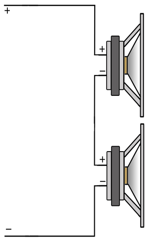
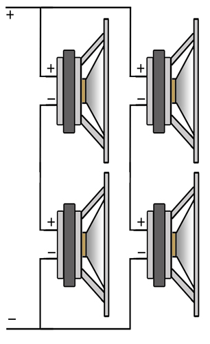
Learn more about impedance and why it matters
Q: If I replace my 400W speakers with 450W speakers will they go louder?
A: Not necessarily. The limiting factor is usually the amplifier. If your amp is rated at 400W, you will not get more than 400W of clean output without distortion and potential amplifier damage. If your amplifier can deliver 450W, higher power handling may allow slightly higher output, but it may make no difference at all, and in some cases the speaker may even be quieter.
The key factor is efficiency. Some speakers convert electrical power into sound more effectively than others. If two speakers are operating at the same power level, the more efficient one will be louder. This is normally indicated by the sensitivity rating, measured in dB @ 1W / 1m.
Efficiency and Sensitivity
Q: Which power rating should I look at?
If you’re new to this, the most useful figure is the continuous power rating, usually specified using the AES standard. This gives a sensible indication of how much power a driver can handle of ‘continuous sound’ under realistic conditions and is the figure most manufacturers now quote.
You may also see a program or music power rating, which is typically around twice the AES rating. Peak power ratings are often quoted as four times the continuous rating and are of little practical use. If you see a peak figure, dividing it by four will usually give a reasonable idea of the true continuous power capability.
Q: What do the power ratings mean?
Continuous / “RMS” Power. Historically, loudspeaker power ratings were often quoted using continuous sine-wave tests, sometimes at a single frequency such as 1 kHz. These tests were easy to define and repeat, but they were not representative of real music and placed unusually high thermal stress on the voice coil.
The term “RMS power” is technically incorrect, as power itself does not have an RMS value; RMS applies to voltage or current. The RMS voltage is used in the power calculation, which is where the term originated. While RMS is useful for steady, resistive loads such as heaters or cable thermal calculations, it is not an ideal way to describe how loudspeakers behave with dynamic audio signals.
As a result, RMS power has largely been replaced by standardised noise-based tests that better represent music and broadband programme material, most notably the AES standard.
Over the years, manufacturers have used several recognised standards (a few still reference older ones):
- IEC 268-5 (1978) – International Electrotechnical Commission
- EIA RS-426-A (1980) – Electronic Industries Association
- AES2-1984 – Audio Engineering Society
- AES2-2012 – now the most widely adopted standard
When many manufacturers moved from the EIA standard to AES testing, some drivers saw power ratings increase by 25% or more without any physical design changes. One example we are aware of is a high-power 18″ driver that was re-rated from 600W to 800W purely as a result of the change in test method.
How is this possible? The AES standard defines a broadband pink noise signal with a specified crest factor for power testing, which differs from older methods. Many manufacturers implement the AES test using controlled noise over a defined period to stress the voice coil thermally, and this often results in higher quoted power figures compared to older standards. While the exact test duration and setup can vary by manufacturer, the AES rating provides a more consistent benchmark for comparing loudspeaker power handling.
Music / Program Power.
Often quoted as Program or Music power, this figure is typically defined as twice the continuous (AES or equivalent) power rating, representing a +3 dB increase. This does not mean the loudspeaker can handle twice the average power. Instead, program power allows for higher short-term peaks while the long-term average power remains the same as the continuous rating. In practical terms, this corresponds to a signal with a higher crest factor than the standard continuous test signal.
Real music contains peaks and valleys rather than a constant energy level. Program power reflects this by permitting greater instantaneous power during musical transients, provided the average power over time does not exceed the continuous rating. For system design, program power is best viewed as a headroom figure rather than a usable continuous operating level. Treating program power as a sustained power rating will almost certainly result in loudspeaker damage, however program power is useful for calculating amplifier power to get sufficient headroom. Opinions vary but most people suggest getting an amplifier slightly larger than AES power is a good start. If you want decent headroom, maybe aim halfway between AES Power and Program power – but at this point you have to start exercising caution with compressors and limiters to ensure the long term power rating does not get too high.
Peak Power:
This is the maximum very short-term power a driver can survive, and is typically quoted as four times the continuous (AES) power rating, representing a +6 dB increase. It exists almost entirely as a theoretical limit and has little relevance to real-world system design.
Peak power should not be used for amplifier matching, system sizing, or safe operating levels. Its primary practical use is for marketing, or for impressing someone who doesn’t know anything about sound.
Should I buy the most powerful speakers I can afford?
Probably not. It’s usually better to choose speakers that are appropriate for your amplifier power and intended use.
High power drivers are typically designed to survive large amounts of electrical and mechanical stress. This often involves design trade-offs such as heavier moving parts, longer voice coils, and suspensions optimised for high excursion. While these features increase power handling, they do not automatically increase efficiency.
As a result, a very high power driver is not necessarily louder at low or moderate power levels than a lower power driver with higher sensitivity. If you compare two extreme examples, such as a 100W driver and a 1000W driver, both driven from a 100W amplifier, the lower power driver may actually produce more output simply because it converts the available power into sound more efficiently.
The higher power driver only begins to show its advantage when sufficient power is available to drive it closer to its intended operating range. With a larger amplifier, it will ultimately produce far more output than the smaller driver ever could. However, when amplifier power is limited, choosing a driver with power handling far in excess of what the amplifier can deliver offers little benefit, and could be detrimental. Typically a 1000W woofer can be heavy and inefficient compared to a 200W woofer. On a smaller amp of 200W, the 200W woofer could actually play louder than the 1000W woofer which is inefficient.
In short, more watts on the specification sheet do not guarantee more sound. Sensitivity and appropriate system matching matter far more than headline power ratings.
So what if I exceed the power ratings?
You run the risk of overheating the voice coil and causing thermal failure. However, staying within the recommended power rating is not a guarantee of reliability.
Loudspeakers can also be damaged mechanically through excessive cone movement. This is described by excursion limits such as Xmax and Xlim. It is entirely possible to destroy a driver through over-excursion without ever exceeding its rated power, particularly at low frequencies or in poorly controlled enclosures.
There is also an important interaction between excursion, bandwidth, and cooling. In some situations a driver can reach its thermal limits at power levels well below its rated AES power.
For example, running a loudspeaker over a very narrow pass band (such as 30–40 Hz) in a cabinet tuned close to that frequency can result in extremely low cone excursion. While this may reduce mechanical stress, it also reduces air movement around the voice coil. Since many drivers rely partly on cone motion to aid cooling, limited excursion can significantly reduce heat dissipation.
In these conditions, particularly in small enclosures with restricted airflow, the usable thermal power handling may be substantially lower than the published AES rating. In extreme cases it can be closer to 50% of the rated value, despite excursion remaining well within safe limits.
What about Power Compression?
Power compression is the hidden problem that can upset even the best-planned systems and make published specifications feel misleading. Many manufacturers choose not to quote power compression figures at all, and some avoid mentioning it entirely.
Loudspeaker sensitivity is specified at 1 W measured at 1 m. At this very low power level, the voice coil remains cool and the driver is highly efficient at converting electrical energy into sound.
In real use, voice coils heat up. Most are wound with copper, which has a positive temperature coefficient of approximately 0.39% per degree Celsius. It is entirely possible for the voice coil of a high-power driver to reach temperatures approaching 200°C, resulting in a resistance increase of 50% or more.
As the voice coil resistance rises, the effective impedance of the driver increases. An 8 Ω loudspeaker may behave more like a 13–14 Ω load at high power. The amplifier delivers less current, acoustic output drops, and a significant proportion of the input power is lost as heat rather than sound.
The practical result is reduced output at high drive levels. A well-designed driver with good thermal management and low power compression can be 3–4 dB louder at full power than an otherwise similar driver that suffers heavily from compression. For this reason, modern high-quality designs place increasing emphasis on cooling and heat dissipation to minimise power compression.