AES Power, Program Power, and Amplifier Power Explained
Power ratings in audio are confusing because they try to describe something that is constantly changing. Music is not a steady signal, yet power ratings are often presented as if everything operates at a fixed level. To make sense of AES power, program power, and amplifier power ratings, it helps to think in terms of power over time, rather than a single number.
Summary
AES power describes how much power a loudspeaker can handle on average over time. Program (music) power allows for higher short-term peaks, not higher continuous power. Real music delivers power in bursts rather than as a constant load. Modern amplifiers, especially Class D designs, are very good at producing high peak power briefly, while long-term power is limited by heat, power supplies, and mains capacity. The aim of this article is to show how average power, burst power, and time are related, and why a headline figure such as a 2000 W peak can be entirely real while still not representing the long-term power demand of a system. By looking at how music behaves over time, and using simple visual examples, it becomes much easier to understand how loudspeaker ratings, amplifier ratings, and even 13 A mains plugs all make sense in practice.
AES Power vs Program (Music) Power
Modern loudspeaker drivers are usually specified with two related power figures: continuous power (often defined using the AES standard) and program or music power.
AES power represents the long-term average thermal capability of the loudspeaker. It indicates how much power the voice coil can safely dissipate as heat over time using a defined broadband test signal. In simple terms, AES power is a safe long-term operating limit.
Program (music) power is typically quoted as twice the AES power, which corresponds to a +3 dB increase. Importantly, this does not mean the loudspeaker can handle twice the average power. The long-term average power remains the same as the AES rating.
The difference between AES and program power is not extra heat capacity, but crest factor. Program power allows for higher short-term peaks while keeping the long-term average unchanged. The signal is allowed to get taller for brief moments, but not heavier overall.
To understand why this distinction matters, it helps to look at how power is delivered over time.
Power over time: short, high peaks
In the first diagram, the vertical axis represents instantaneous power, and the horizontal axis represents time. The shaded red areas show when power is being delivered.
The diagrams are illustrative rather than literal. Their purpose is to explain concepts, not to define exact test conditions or limits.
Figure 1: Short-duration, high-peak power delivered in brief bursts over time.
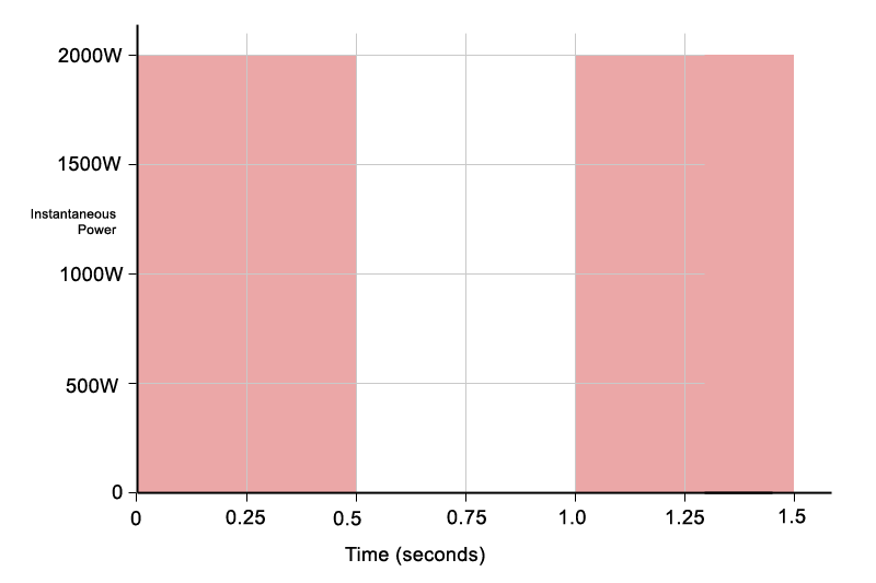
Each rectangle represents a short burst of power:
- Peak power: 2000 W
- Duration: 0.5 seconds
Power multiplied by time gives energy. A 2000 W burst lasting 0.5 seconds delivers the same energy as 1000 W delivered for a full second:
2000 W × 0.5 s = 1000 W × 1 s
Although the instantaneous power is high, it is only present briefly. When averaged over a longer time window, the effective power is much lower. This is the key idea behind program power: higher peaks are allowed, but they do not increase the long-term average.
This type of power delivery closely resembles real music. Bass hits, kick drums, and transients are short, intense bursts separated by quieter moments.
To make the diagrams easier to understand, I have intentionally used simple numbers, 2000W, 1000W, 0.5 seconds – it makes the maths much easier. You can see each red rectangle is divided up into 8 smaller rectangles, which is easy to visualise.
Same energy, delivered differently
In the Figure 2, the same total energy is delivered in a different way. Instead of short peaks, power is delivered continuously. This is similar to electrical systems such as heaters, power is delivered continuously to a static load, the power level does not go up or down, it remains constant. Music is not like this, amplifier and music power is dynamic, and constantly changing. The power an amplifier delivers to the speaker, and draws from the mains supply varies with time.
Figure 2: The same total energy delivered as lower, continuous power over the same time period.
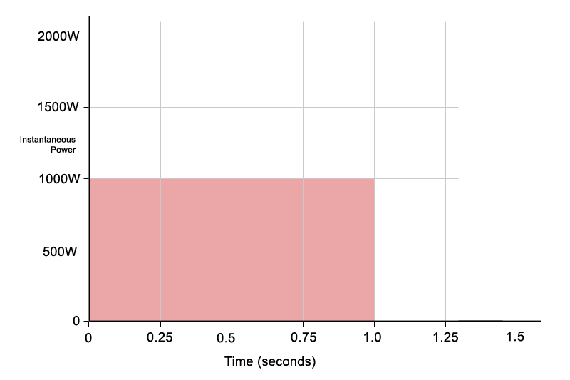
- Power level: 1000 W
- Duration: 1 second
The shaded area is the same size as in the Figure 1, which means the total energy is identical. The average power is also the same. You can see this visually: the area still covers exactly eight grid squares, just arranged differently.
In this example, the continuous 1000 W case does not represent a significant challenge for the amplifier. An amplifier capable of delivering 2000 W peaks will typically have no difficulty sustaining 1000 W continuously, as the average power and thermal load remain well within its design limits.
The real limitation appears when high power is sustained for longer periods. While short bursts of 2000 W are easily achievable, maintaining that level for several seconds places extreme demands on the power supply and output stage. Voltage rails sag, current limiting engages, and thermal protection may begin to operate.
This is where many Class D amplifiers reach their limits. They are designed to deliver very high short-term power with ease, but they are not intended to sustain maximum output continuously, particularly at low frequencies.
What this means for loudspeakers
From the loudspeaker’s point of view, heating depends on average power over time, not peak power. The voice coil does not care whether energy arrives in short bursts or steadily; what matters is how much heat builds up overall.
AES power therefore describes a realistic long-term thermal limit. It represents the average power a loudspeaker can dissipate safely over time without overheating. In the simplified examples shown here, this is illustrated by the second diagram, where the average power level remains constant.
Program or music power acknowledges that real music is dynamic and contains peaks and lulls. This is illustrated in the Figure 3, where the total shaded area remains the same, but the instantaneous power rises to higher peaks. The average power is unchanged, the program material just has a higher crest factor with more pronounced peaks and lulls.
Figure 3: Illustrating crest factor for music/program power.
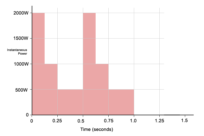
This simplified example shows how a loudspeaker can safely handle higher short-term peaks, provided the long-term average power remains within the AES rating. Program power just shows the speaker can handle higher short term peaks, as long as the long-term average power remains within the AES limit.
Problems arise when program power is treated as a continuous operating level. If the programme material has little dynamic range, or if heavy compression and limiting are applied, the crest factor is reduced and the average power rises toward the peak level. In this situation the loudspeaker is no longer operating within its intended thermal limits and the voice coil can overheat.
Program power is therefore best understood as a headroom allowance for dynamic signals, not as a sustained power rating. It best represents live music, particularly percussive sounds. Electronic, synthesised music is often compressed, and has long extended bass notes with low dynamics.
What this means for amplifiers
Modern amplifiers, particularly Class D designs, behave much like the first diagram rather than the second.
They are extremely good at delivering short bursts of high power thanks to high-voltage rails and efficient output stages. This is why many modern amplifiers are rated using standards such as EIAJ, which better reflect burst capability and musical crest factor.
What these amplifiers cannot do is sustain very high power indefinitely, especially at low frequencies. Long, continuous bass notes place heavy demands on the power supply, causing voltage sag, current limiting, or thermal protection to intervene.
This is why amplifier power ratings often look impressive on paper but drop significantly under continuous sine-wave testing, particularly into low impedances.
Matching amplifier power to speaker power
Program power is useful when choosing an amplifier because it indicates how much headroom is available for musical peaks. A common and sensible approach is to choose an amplifier capable of delivering somewhere between the AES power and the program power of the loudspeaker.
This provides enough headroom for dynamics without pushing the driver beyond its long-term thermal limits. However, once amplifier power approaches program ratings, proper use of limiters and compressors becomes essential to prevent excessive average power.
How can this make sense on a 13A plug?
The same power-over-time logic also explains why large amplifiers can operate from ordinary mains supplies. To take this one step further, it is useful to look at a more realistic musical signal rather than a simple rectangle, which represents power being fully on or fully off.
Figure 4 shows a simplified ADSR-style envelope, loosely resembling a typical percussive sound such as a drum hit. The instantaneous power still rises briefly to around 2000 W, but the time spent at high power is much shorter than in the rectangular examples.
Figure 4: A simplified percussive envelope showing brief high-power peak typical of a real musical signal.
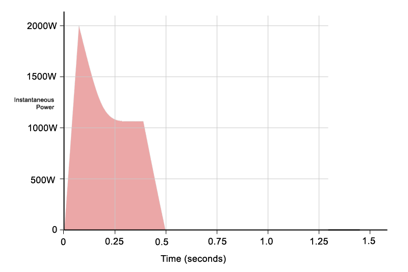
As a result, the total shaded area is smaller, meaning less total energy is delivered overall. Despite the high peak, the average power remains relatively low. This is exactly the type of signal that modern Class D amplifiers handle extremely well: short, high-power bursts delivered cleanly without clipping and distortion. To clarify, this is not intended to suggest that a Class D amplifier cannot sustain peaks for longer than shown – indeed most can. The diagram is simply a representative example of real-world music, intended to show how musical signals translate into long-term average power, and why the ability to handle short bursts of high power is important for preserving dynamics.
This behaviour explains why large amplifiers can produce impressive peak power figures while still operating safely from standard mains connections. The peaks are brief, the average power is modest, and the electrical system only needs to support the long-term average rather than the instantaneous maximum.
For reference, the percussive example above has been approximated into a final diagram (Fig. 5) showing the same energy spread out as continuous power over time. Although the instantaneous peak reaches around 2000 W very briefly, the equivalent long-term average power is much lower, in the region of 600W.
Figure 5: The same energy from Figure 4 redistributed as continuous power, showing the equivalent long-term average.
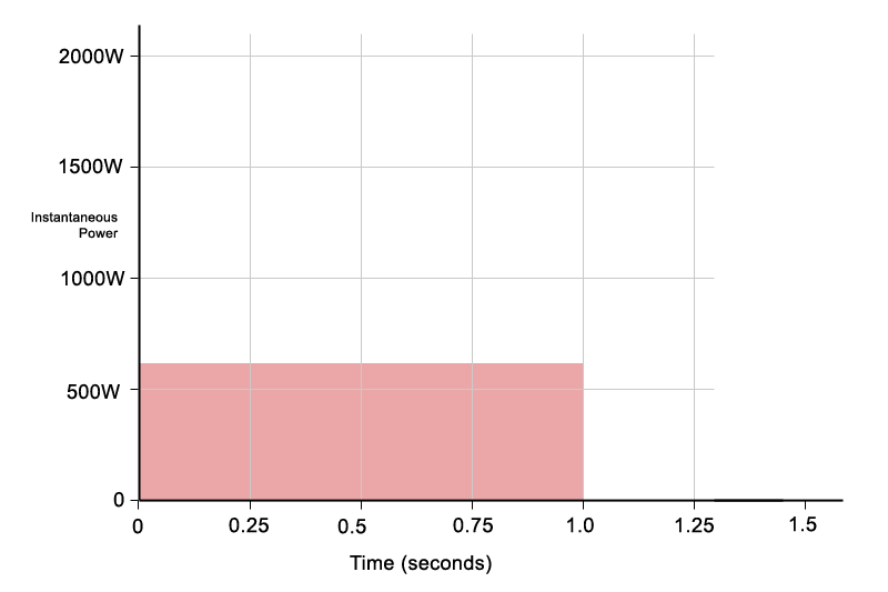
This illustrates an important point: a short, high-power percussive event may look extreme when viewed instantaneously, but when averaged over time it represents a far more modest power demand. Even when additional sounds are present, the medium-term average power may only rise to around 800-900 W.
Applied across a four-channel amplifier, this suggests that even when all channels are working hard, the combined long-term average power is often closer to 3000W rather than the headline peak figures. While this approaches the practical limits of a 13 A mains supply, real music contains loud passages, quieter sections, and natural breaks. These variations reduce the long-term average further, keeping operation within safe limits.
This is why high-power amplifiers can operate from standard mains connections. Peak power figures describe short-term capability, not continuous demand. In the case of amplifiers such as the JAM Systems Q10, which is rated at up to 2500 W EIAJ per channel into 2 ohms, the apparent mismatch between output power and a 13 A plug disappears once power is considered over time rather than at its instantaneous maximum. Realistically this amp is at the limits of a 13A supply, which is why it comes with a heavy duty mains cable with 2.5mm cable and a heavy duty plug.
After being asked countless times how the JAM Systems Q10 can operate from a 13A plug, this article was written to explain exactly that. This article now serves as the standard explanation.
The key takeaway
Power ratings make far more sense when you consider how power is delivered over time. Peak power, program power, and amplifier ratings all describe different aspects of the same thing: short-term capability versus long-term limits.
Many people dismiss peak power figures because of how terms such as PMPO were misused in consumer hi-fi, often wildly overstating real capability. However, genuine high burst power serves a real purpose. It allows the dynamics of the original programme material to be preserved, delivering very large transients when required, but only for short periods of time.
AES power defines what is safe on average. Program power defines how much headroom is available for musical peaks. Understanding the difference makes amplifier choice, system setup, and real-world behaviour far easier to predict.