Possibly one of the most misunderstood parameters, most people know Xmax concerns driver excursion, but dont really know precisely what it means, and it is probably the name that confuses people, as it is slightly misleading.
We’re used to letters X and Y denoting dimensions, and in this case, X does relate to a dimension, it’s to do with the distance a loudspeaker’s voice coil travels back and forth, so it’s all good so far – but the ‘max’ is what throws people. Its natural to assume max means maximum, and the conclusion most people reach is that X max means maximum excursion in dimension X, which is nearly right. What’s missing is the word linear. Xmax is generally regarded as maximum linear excursion – but what exactly does that mean?
Let’s look at a simplistic way of how Xmax is often calculated (this applies to overhung voice coils – which is most common in high power loudspeakers)
The Formula is: (HVC – HG) / 2
Where HVC is the Height of the Voice Coil, and HG is the Height of the magnetic Gap.
To understand this we need to look at how the components of a loudspeaker fit together, this is a simplified cross-sectional diagram of a common loudspeaker.
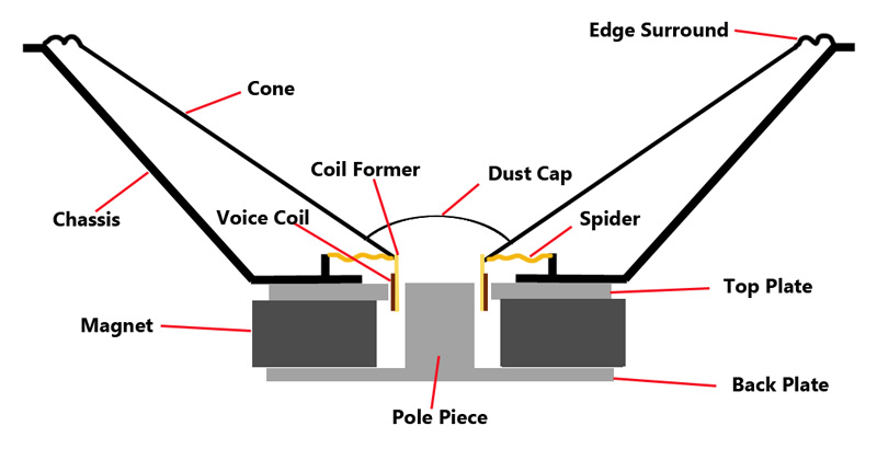
Cross-sectional diagram of a typical loudspealer
Now, let’s look in more detail at the area around the voice coil, we’ve removed the right hand part of the voice coil to make the diagram clearer.
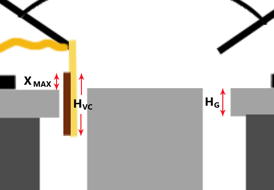
Voice coil in magnetic field, showing Xmax and Magnetic Gap Height
You can probably now see why Xmax is often referred to as Voice Coil Overhang. It’s the amount by which the voice coil overhangs the magnetic gap, but why is this significant?
Let’s take a closer look at the static magnetic fields in a loudspeaker. These are the fields generated by the magnet, rather than the fields generated by the voice coil.
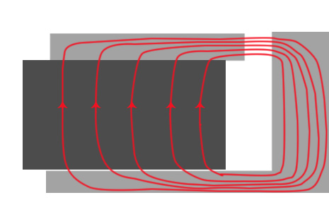
Magnet structure and magnetic flux (simplified)
This is a simplified diagram, intended to show the most significant path of magnetic flux. There will also be stray flux outside the speaker, and inside the air gap between the magnet and pole piece, and in a real speaker, the field lines are unlikely to quite as uniform as in the above diagram, but it should be sufficient to see the general principle of how the magnetic field is acting. The permanent magnet has a north pole at one end, and a south pole at the other. Depending on the speaker manufacturer, it’s normal for the pole piece to become the ‘north pole’ and the top plate to become the south pole. The shape of the top plate, and pole piece helps focus the magnetic flux, and you will notice the lines of flux are closest together in the magnetic gap – where the voice coil would normally be.
Since ferrous materials are much more magnetically permeable than air, by a factor of about 400. Magnetic flux will tend to take the route of least resistance, in much the same way as electricity does, this will mean the magnetix flux will tend to want to travel through the metal parts of the speaker. Where it reaches the gap it will continue to go down the route of least resistance, which in this case will be the shortest distance through the air, ie straight across the gap. The flux is squeezed together across the gap, causing the flux to flow in parallel lines across the gap, creating a uniform, linear magnetic field.
Traditionally Xmax was calculated mathematically using the simplistic formula mentioned earlier, this is because many earlier speaker designs used relatively weak magnets, and it was assumed that the magnetic field would drop off very significantly just above or just below the gap, and would be of little or no use.
When you pass electrical current through the voice coil, it will create its own electromagnetic field, which will push against the magnetic flux in the voice coil gap, causing the voice coil to move. If you keep driver excursion within Xmax, there will always be the same height of voice coil within the gap. The diagrams below show the maximum excursion in each direction to keep within mathematically calculated Xmax. Since the magnetic field in the gap should be linear and uniform, and the height of voice coil within the gap remaining constant, mathematical models can be created to predict driver behaviour. Working outside Xmax will cause those mathematical models to become inaccurate, as well as potentially introducing distortion and other poor performance.
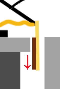 Maximum back excursion |
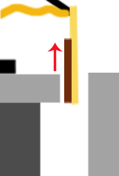 Maximum forward Excursion |
Moving the voice coil any further up or down in either direction, as in the diagrams below, would cause the height of the voice coil that is within the magnetic gap to become shorter, shown by the red arrows. You can clearly see this is less than the Gap Height. Less Voice Coil in the magnetic gap, means less pushing force moving the cone, which is where the non-linear behaviour starts, hence the term maximum linear excursion. The cone will still move, but it will no longer be optimal performance.
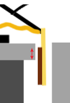 Xmax exceeded |
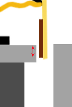 Xmax exceeded |
It is becoming increasingly common to use stronger magnets in modern designs, which can sometimes mean that useful magnetic flux (although slightly weaker) will also be present just outside the gap, and magnetic field strength may still be acceptable in this area. Depending on the magnet strength, and other factors, Xmax when consider to be a measure of maximum linear excursion can actually be 25%-40% larger than mathematically calculated Voice Coil Overhang.
So when you are comparing one brand of driver to another, you need to be aware that the Xmax figures may be calculated differently, and a driver with a specified Xmax of 7mm from one manufacturer (using Voice Coil Overhang) could in fact have a very similar performance to one from another manufacturer with an Xmax of 10mm, who has perhaps used a different mathematical model and/or tolerance to determine the limit of linear excursion.
The best solution may be to determine Xmax by measurement rather than simple maths, and there is a growing trend towards using Klippel Analysis to determine Xmax more accurately, the driver is progressively driven to high levels at low frequencies, and Xmax is determined by measuring excursion at a level where 10% THD is measure in the output. This is believed to better represent actual driver performance, however is quite time consuming, and can be difficult to measure, consequently many manufacturers do not bother.
What is the significance of Xmax?
Cone excursion is related to loudness, especially with deep bass frequencies in a bass reflex cabinets. To reproduce bass frequencies at high volume you need to move a lot of air, and to move that air your speaker cone needs to move a lot. A bass driver with a low Xmax will generally not be designed to reproduce bass frequencies at high power, as it simply can not move enough to do the job. There is an exception to this in horn loaded bass cabinets, where excursion can be restricted, and Xmax may be less critical, depending on the design.
Will exceeding Xmax damage the speaker?
Not necessarily, some manufacturers will also specify Xlim or Xdamage which is the maximum mechanical excursion before damage is expected, this can often be double Xmax. The two will often be related, a driver with a large Xmax designed for long excursion, will usually be designed such that Xlim is proportional to Xmax. Xlim is often regarded as maximum mechanical excursion, as this is the point where you will cause mechanical damage if you exceed this, most commonly with the end of the voice coil hitting the back of the speaker and damaging the voice coil former:
Exceeding Xmax
You can in most instances exceed Xmax without causing mechanical damage to the voice coil, however you should take note that exceeding Xmax can reduce the power handling due to detrimental effects on voice coil cooling.
Depending on the driver design, other things to consider when exceeding Xmax is the mechanical stresses on the speaker components, such as the spider, and where the spider joins the cone and coil former. There is potentially a large force acting on these components, stretching and pulling them beyond their designed limits. Whilst you can often exceed design parameters a little without causing damage, it would not be a sensible idea to exceed Xmax significantly as you will reduce the useful working life of your speaker.


