You’ve most likely seen coils of copper wire in audio filters, but what do they do? and how do they work? We’ll try to give a simple explanation here.

At the most basic level, and inductor is just a coil of wire, and the design and construction of the inductor determine it’s inductance, which is usually measured in millihenries. Larger value inductors tend to be needed for low frequency filters, perhaps as big as 4 or 5 millihenries, but much lower value inductors are needed for higher frequency audio applications, typically between 0.1mh and 1.5mH for most common 2 way crossovers.

So, how do they work? It gets a bit sciencey, so we’ll try to keep it simple. When current flows through a wire, it creates a magnetic field around the wire. When the wire is wound as an inductor, the magnetic fields from various sections of the inductor will each have an effect on other parts of the inductor, creating a electro-motive force within the wire/inductor that opposes the applied voltage to the inductor. In effect creating an electric force in the wire that’s opposite to the voltage that’s being applied. At low frequencies, the opposing force is very small, and the inductor acts just like a piece of wire. The opposing force gets bigger and bigger as the frequency goes up, and this makes it more difficult for high frequency signals to pass through the inductor. This allows a single inductor to work as a low pass filter – blocking high frequencies and letting low frequencies pass through.

All you have to do is select the correct value of inductor (in mH) for the cut-off frequency you need for your filter.

Well, if only it were that simple. You then need to decide what type of inductor to use.

Ferrite Core. For low power filters, people have often used ferrite cored inductors. The magnetic permeability of the core increases the magnetic field strength of the inductor, allowing a specified inductance to be reached with much fewer turns of wire. This has the benefit of reducing the resistance of the inductor, making it less lossy, and ensuring more of the power reaches the speaker and less is lost in the inductor as heat. Ferrite cored inductors have a problem, they will saturate at high power levels, when the maximum magnetic field strength has been reached in the core, after this the field cant continue to increase, which causes the inductance to decrease. This causes increased distortion, and is undesirable in audio circuits. Most designers avoid ferrite cored inductors for higher power circuits.

Powdered Iron Core. You could think of these as a ‘premium’ ferrite core – they have similar benefits in terms of fewer turns of wire. They offer improved power levels due to higher saturation point, but this comes at increased cost. Considered a good compromise where ferrite core is too low power, but air cored is too big and expensive.

Laminated Steel Core. Another alternative to ferrite core inductors, but suffering from similar distortion issues especially at higher frequencies, which makes them more suited to low pass filters. The saturation point is lower than powdered iron core, but they benefit from the fact that large value inductors (2mH-4mH) are possible without huge amounts of wire being used, this helps keep the size and cost manageable, and avoids losses due to resistance of the wire.

2.0mH Laminated Steel Core Inductor

Shop for Laminated Steel Core inductors on www.bluearan.co.uk – the UK’s leading loudspeaker components supplier for Pro Audio

Air Core. Ask any audiophile, and just plain simple air is what’s best inside an inductor. The saturation point is typically so high you can achieve extremely high power levels without distortion from saturation. The inductor is generally unaffected by temperature changes, and the core (being air) cant rattle, vibrate or crack, and so is very stable. There is a drawback – particularly at low frequencies – in the the inductors can get quite large and expensive. The size of the inductor can mean losses in the wire, and heat build up, which are not ideal. Imagine your inductor having a resistance of 1-2 ohms when your speaker is 8 ohms – significant power loss can occur in the inductor before the power gets anywhere useful.

0.31mH Air Cored Inductor

Shop for Air Cored Inductors on www.bluearan.co.uk – the UK’s leading loudspeaker components supplier for Pro Audio

Its fairly common for manufacturers to mix different types of inductors in one filter according the required power handling, frequency, and price point. There will always be some compromises, but choosing the best in each situation gets the required result.


Some of the basics of crossovers have been covered in this article: https://speakerwizard.co.uk/loudspeaker-basics-crossovers-why-do-we-need-them/ – here we will go into a little more detail of how passive filters work, and give you the tools to design your own.

Crossovers and Filters

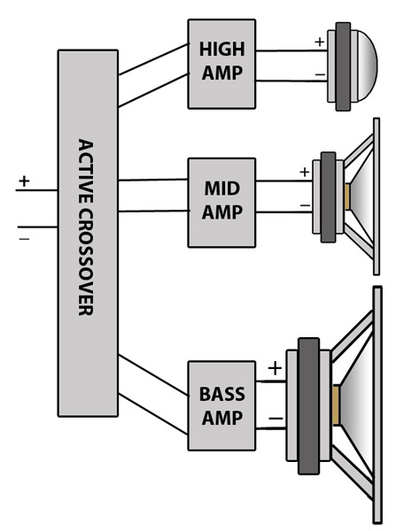
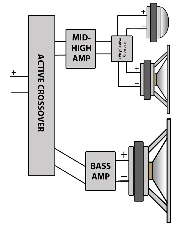
Lets’s start with a reminder of the basics, a crossover is a combination of high pass and low pass filters which split the signal into bands. The most basic crossover is a 2-way crossover, which splits the signal into 2 bands. Common configurations are 3-way and 4-way, which allow better matching of speakers with their appropriate operating range. 5-way active crossovers are not uncommon in large format PA systems in order to help cover as wide a frequency range as possible, as effectively as possible, to maximise various factors such as quality, dispersion, volume, as required by the design criteria. It is possible to keep splitting the audio range into smaller and smaller bands, but this can become an exercise of diminishing returns.

The Basic Building Blocks: Capacitors and Inductors

Capacitors: A Capacitor  has a high ‘resistance’ (commonly known as reactance) to low frequency signals, and a low ‘resistance’ to high frequency signals. When combined with a resistor, you get a filter circuit, as shown in the diagram below.

high_pass_1st_order copy

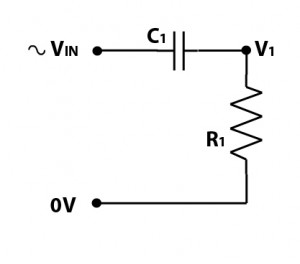
If you’ve ever looked at  a high pass filter , and taken notice of the components, you might be wondering why you don’t have a resistor, its because the resistor in the above circuit is your loudspeaker. This is something to be aware of when using passive filters, that the filter DOES NOT work independently of the loudspeaker, the loudspeaker forms part of the circuit. If you change the load resistance from 8 ohms, to 4 ohms or 16 ohms, you change how the filter circuit works.

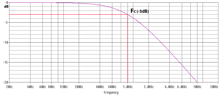
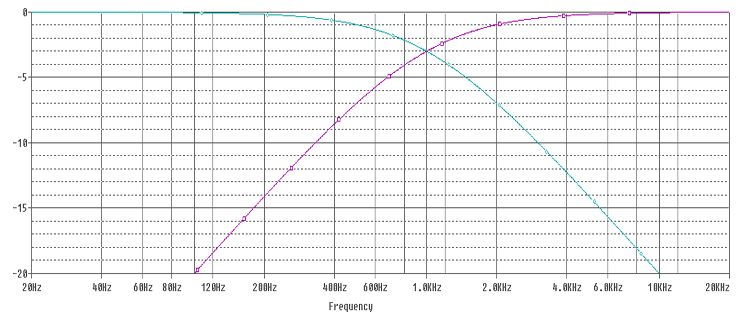
The diagram below shows the relative magnitude of the signal at point V1 with 0dB in the diagram indicating full signal. V1 is the Voltage that will be applied to the loudspeaker (R1). The cut off frequency in the diagram is 1kHz. We use dB scale for audio purposes due to how we perceive  differences in volume of sound, a doubling or halving of magnitude is a significant enough change to be noticeable.

high_pass_plot

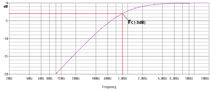
The filter has a cut-off frequency, commonly known as FC. Below the cut-off frequency, the capacitor has a high resistance, effectively blocking the signal. The purple line represent the magnitude of the signal that will pass through the filter. You can see that as the frequency reduces, the magnitude of the signal passing through the capacitor reduces.  The point where the purple line crosses -3dB is at  the cut off frequency, where the capacitor ‘resistance’ will be approximately equal to the resistor in the circuit.  With the capacitor and resistor being roughly equal, the system will work as a voltage divider, with approximately half the input voltage across the capacitor, and half the voltage across the resistor (loudspeaker). FC is sometimes known as the -3dB point, where -3dB indicate half magnitude.   Beyond the cut off frequency the capacitor reactance reduces, allowing higher frequency signals to pass unhindered. At these higher frequencies a ‘pure’ capacitor would have no effect on the passage of signals whatsoever, unfortunately pure capacitors are theoretical, and impossible to manufacture – any capacitor used in a filter circuit will also have a small constant resistive component and some inductance also – these contribute to distortion within the  signal, as well as power losses. Higher quality capacitors are designed to be closer to a ‘pure’ capacitor and minimise losses and distortion within the capacitor.

Calculations for 1st order High Pass Filters

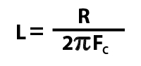
The resistance value (measured in ohms), and the capacitance (measured in farads)  determine the cut-off frequency as per the following formula:

fc_formula


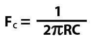
In our examples above , R1 is 8 ohms, and C1 is 20uF (microfarads). To use the formula above you need to use the capacitor value in farads, 20 uF = 0.000020 farads. Pi is  the mathematical constant, you can use pi to 2 decimal places (3.14) for purposes of calculating filters. If you put the numbers into the formula, you’ll get FC of 994Hz.

As mentioned previously, the loudspeaker impedance forms a part of the circuit, if you try the formula you will notice that increasing the impedance from 8 ohms to 16 ohms will halve the cut-off frequency and reducing the impedance from 8 ohms to 4 ohms will double the cut off frequency.  This is why you should only use a passive crossover or filter with the correct impedance load it has been designed to operate at.

We can change the formula to make it more useful, as we usually know what cut-off frequency we want, and what the resistance (impedance) is, but what we need to calculate is what value capacitor. This formula will yield the correct results:

C Formula

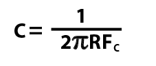
You must use FC in Hertz, and NOT kiloHertz to get the correct answer.

If you’re not so keen on maths, you can use our calculator to help (kHz/uF units are handled automatically)


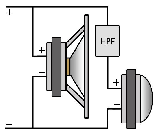
 A first order filter is generally sufficient as a tweeter protector in an active system. You can add a capacitor in series to protect against DC Faults and/or accidental connection to a bass amplifier. You should make Fc of the capacitor  one octave lower than the Crossover Frequency on your active crossover to avoid any problems. One octave lower is exactly half the freqency, so if your compression drivers are operating from 2kHz upwards, your tweeter protector should be selected to operate at 1kHz. The calculator above will give suitable results for this application. Some people would argue that is is better to use a 2nd order filter, due to the phase shift caused by the filter (We’ll discuss this in another article).

Multiple Capacitors:

When using capactiors in filter circuit, you should  be aware that  capacitors in series/parallel sum differently to resistances, in fact the rules for capacitors are opposite to how series/parallel resistances combine. Two equal resistors in parallel will halve the overall resistance, however two capacitors in parallel sum together. So two 10 microfarad capacitors in parallel are equivalent to one 20 microfarad capacitor. Two resistors in series, sum together to increase the resistance, capacitors in series give a smaller overall capacitance:  two 10 microfarad capacitors in series will give an overall capacitance of 5 microfarads. Putting capacitors in parallel is a handy way of making up capacitance values that are not easily available off the shelf. You wouldn’t normally put capacitors in series in a filter circuit.

1st Order High Pass Filter: 

A single capacitor when used with a loudspeaker, forms the most basic High Pass Filter, which is known as a 1st order filter. However, capacitors on their own are not enough to form crossovers, we also need inductors.

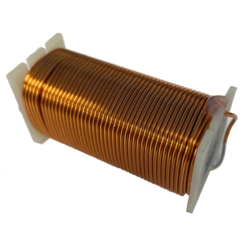
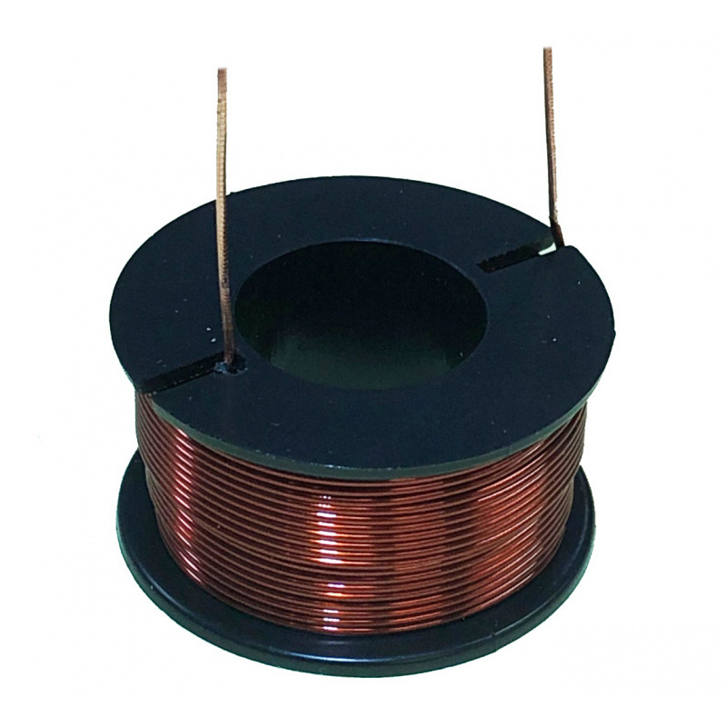
Inductors: Most commonly these are coils of wire, copper is most commonly used as it has a low DC resistance.  In fact a straight copper wire would be what you normally use to connect up your speakers, so how does it form part of a filter? When current flows through a wire, an electromagnetic field forms around the wire, in a straight wire this field does not easily interact with other parts of the wire, so the effects are negligible, however, winding the wire into a coil creates a larger magnetic field. This magnetic field induces a voltage in the wire which opposes the current flow that creates it, this is often known as back EMF (electro motive force)  So every time there is a change in current, the inductor creates a back EMF to try to stop the change in current.

An inductor has a low resistance to low frequencies. An inductor’s lowest resistance is it’s DC resistance,  you can think of DC as a 0Hz signal.  Inductors allow DC to pass, as once current is established, there is generally no change in current. Inductors block or resist AC, or alternating current, and an audio signal can be regarded as a form of AC.

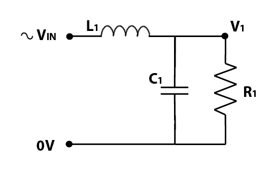
The circuit below shows an inductor and a resistor, forming a simple low pass filter.

low_pass_circuit

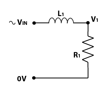
Again, the R1 is the loudspeaker,  and L1 represents an inductor.  For our example, we will make L1 equal to 1.27mH (milliHenries), which is written as 0.00127 H. With an 8 ohm loudspeaker for R1 we get the following frequency response:

low pass graph

Inductors behave like resistors for purposes of summing their values. Two inductors in series sum together to create an equivalent bigger inductance in much the same way as two resistors in series are equivalent to a higher resistance. The formula for calculating the cut-off frequency is therefore different to the one for capacitors:

fc_formula_L

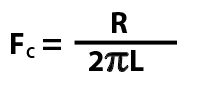
You can test the formula for our example, where R = 8 ohms, and L = 0.00127 Henries. You will get an answer very close to 1000Hz.

Re-arranging the formula makes it more useful, allowing the required inductance to be calculated for a desired cut-off frequency.

L Formula


In that same way as it has not been possible to create the ‘perfect’ capacitor, there has also not been an ‘ideal’ inductor created to-date. The nearest that has been achieved is a  supercooled inductor. All real world inductors have a series resistance created by the copper (or other metal) wire used to make the coil. This series resistance generates some heat, and causes losses in the circuit. Using an inductor with thinner wire will create more losses, so it’s best to choose an inductor with the thickest wire thats available and affordable in order minimise losses.
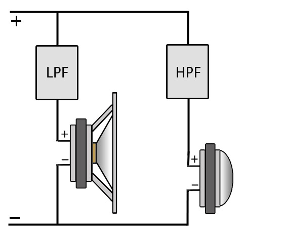
single inductor in series with a loudspeaker forms the most basic Low Pass Filter, this is known as a 1st order filter. A low pass filter (an inductor) and a high pass filter (a capacitor) together form a crossover, splitting the sound two ways, with the bass passing through the low pass, and the treble passing through the high pass.

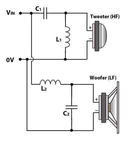
Simple 1st Order Crossover:

crossover circuit 1

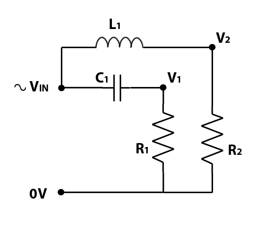
R1 represents a tweeter, operating at higher frequencies only, and R2 represents a woofer, operating at lower frequencies only. To create the above circuit, we have simply combined the circuits for the separate low pass filter and high pass filter. We’ll continue with the same component values of 20uF and 1.27mH, which will give the same cut-off frequency, and we’ll combine the two frequency responses into one graph.

crossover_plot_1

The blue line represents the frequency response of the low pass filter, and the purple line the frequency response of the high pass filter. You’ve probably already realised the significance of the crossover frequency, where the purple and blue lines ‘cross over’ each other and the  graph probably starts looking quite familiar if you’ve ever looked into how crossovers work in the past. If nothing else, you should notice that the point where the two lines cross is at -3dB (half magnitude), if you sum the two responses together you are back at 0dB. So at the crossover frequency, both the woofer and tweeter should be producing the same sound, but each at half magnitude.

In a typical crossover, adding together the bass response and treble response should give you a flat response across the whole frequency spectrum – except there is a problem, inductors and capacitors cause phase shift, and a 1st order filter causes a 90° shift – inductors and capacitors cause phase shift in opposite directions, which would mean the bass and treble are directly out of phase with each other. Near the bottom of the frequency spectrum, you’ll have bass only, coming out of your woofer. At the top, you will have treble only, coming out of your tweeter. To some extent, it doesnt matter if these are out of phase with each other, as they are independent of each other and do not interact, however, around the cut off frequency, both the woofer and tweeter are creating the same frequencies, and if they are directly out of phase with each other, they can cancel each other out – bad news for creating a flat frequency response. With first order filters, this is fairly significant.

If you’re not sure what phase is, or what this means with respect to sound – we’ll cover this in a different article to be published at a later date.

The other problem with 1st order filters is that they are not that effective at splitting the sound, they reduce the magnitude of the stop band by only 6dB per octave, it can take two or more octaves to reduce the sound passed sufficiently, this means that quite a lot of treble still leaks into the bass, and a fair bit of bass leaks into the treble. For better quality sound, it is desirable to restrict frequencies to appropriate speakers, and to do this we need to use higher order filters. For passive crossovers, 2nd order filters are generally regarded as sufficient, occasionally with 3rd order filters used on the high pass only, to help protect tweeters from unwanted bass frequencies.

So how do we make a 2nd order filter?

If this is all new to you, you might think that you can just put two 1st order filters in series to create a 2nd order filter – in some parts of electronics this will work, passive RC filters  can be cascaded to create higher order filters. With loudspeaker filters, the R is the loudspeaker, and you only have one of them, and it’s part of the circuit, so we have to be a bit more clever.

Its not possible to just use two capacitors in series, as these are just equivalent to one capacitor with a different capacitance. Two capacitors in series will just change the cut off frequency, it wont give you a 2nd order filter

To make a 2nd order order high pass filter, we start with our capacitor, but we then add a low pass filter (inductor) in parallel with our loudspeaker, as per the diagram below.

2nd order High Pass

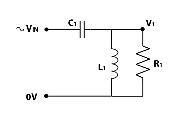
Frequencies below the cut off frequency are blocked by the capacitor, whats interesting is what happens around the cut-off frequency. With a correctly selected inductor, at the cut off frequency, the inductor blocks high frequencies, so these are forced to go through the loudspeaker, but the inductor allows frequencies at or below the cut off frequency to pass – creating a short cut , bypassing the loudspeaker. The result of the capacitor and working together at the cut-off frequency is to increase the slope from 6db/octave to 12 db/octave, a significant improvement.

1st and 2nd order High Pass

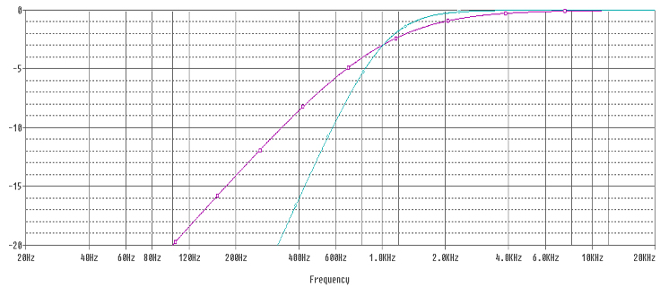
The purple line is the response from a 1st order High Pass Filter, and the blue line the response from a 2nd order High Pass Filter. Both are Butterworth filters. The 1st order filter is a 20uF Capacitor on its own, the 2nd order filter is a 14uF capacitor and a 1.8mH inductor.

You’ll notice the point the responses pass through the -3dB point remain the same for both filters. Selecting the correct values of capacitance and inductance is important for this to work correctly. Where both inductor and capacitor are active around the cut off frequency, the values of the inductor and capacitor have to be adjusted to make the filter operate in a desirable manner. The maths starts getting more involved, and unless you want to get into the finer points of crossover design, its probably easiest just to use one of the crossover calculators that are available online (we will be making ours live very soon)

In more advanced designs, it is possible to tweak the values  to give a different Q. In a Butterworth filter the Q is 0.707, and these are the most commonly used filters in passive crossovers.

Amongst other things, different Q filters alter the shape of the ‘knee’, or bend, where the filters response changes from the stop band to the pass band. Changing the shape of the slope around the cut off frequency can have a significant impact on how the low pass and high pass signals sum. A shallower softer slope (such as a Bessel filter with a Q of 0.5) can result in a ‘hole’ in the response. An optimal slop, such as Linkwitz-Riley or Butterworth aims to keep the overall summed response flat across the crossover frequency. High Q filters, such as Chebychev are rarely used, as these  will tend to give peaks in the frequency response, as well as other undesirable effects.

Higher order filters:

We can continue adding capacitors and inductors alternately to create higher order filters, as per the diagrams below:

3rd order high pass


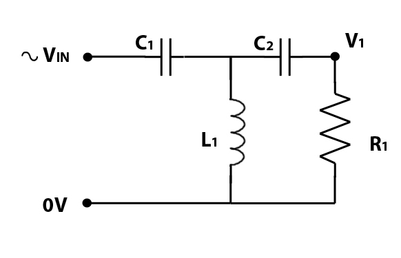
C2 is added to make a 3rd order High Pass Filter.

4th order high pass

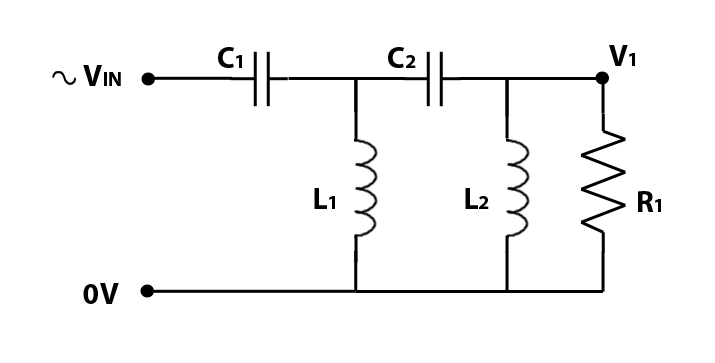
and then L2 is added to create a 4th order high pass filter.

In passive loudspeaker crossovers its rare to see filters higher than 4th order, and even 4th order filters are not very common due to the increased cost of additional components.

Higher order Low pass filters can also constructed in a similar manner to high pass filters, with the components working in a similar manner as high pass filters. In a 2nd order low pass filter, the capacitor acts as a bypass across the loudspeaker, creating a short-cut for high frequencies to skip past the loudspeaker. Where inductors and capacitors are efffectively ‘opposites’ of each other for purposes of passive filtering, to create a low pass filter, the positions of the inductors and capacitors within the circuit are swapped over. The diagram below shows a 2nd order low pass filter.

2nd order Low PassYou can follow the same pattern to work out the configuration of 3rd order and 4th order low pass filters.

Depending on the crossover design, you use corresponding low pass filter and high pass filters to achieve the desired result. If you’re new to this, I would suggest sticking to 2nd order filters on both the low pass and high pass section.

Beyond Passive crossovers?..

If you’ve understood all of this, you should now know how passive filters and crossovers work. Many early active crossovers used the same principles, but using just RC filters with op-amps in order to split the signal before it reaches the power amplifier stage. Many early active crossovers had fixed frequencies, and could not be easily adjusted, a common means of customisation was to have plug in modules, with different capacitors and resistors relating to different configurations of frequency. Innovations in circuit design and improvements in component availability allowed variable frequency active crossovers to be built, back in 1990s, I recall the Rane AC23 becoming available, this was regarded as a high quality, but affordable variable frequency active crossover, I seem to recall they cost around £300, which back in the mid 90s wasnt cheap! A few years later, designs similar to this started becoming commonplace in the industry, and are now used in virtually all variable frequency analog active crossovers that are commercially available today, with prices now in the £50-£100 range.

The revolution in digital processing has now surpassed this, and  most people prefer digital signal processing for active crossovers, mainly due to the massively increased versatility.

2 Comments so far. Join the Conversation
   

Thiele Small Parameters

Posted By Andy Kos

The Thiele Small Parameters (often referred to as T/S Parameters) are provided in specification sheets by most manufacturers – but what are they for? If you read through the section on parameters you’ll get a more detailed explanation on the significance of each parameter, but put simply they are a set of parameters which define the electromechanical properties of the loudspeaker driver, which are a measure of how it behaves electrically, and mechanically.

Once you understand some of the basics of the Thiele Small parameters, you will know what to look for when it comes to choosing a loudspeaker driver. If you’re not interested in the nitty gritty, then it’s probably sufficient to be aware that the parameters are normally used when it comes to doing simulations of loudspeaker behaviour for purposes of optimising cabinet design.

For those of you who are keen to understand a little more about these parameter, you should find almost everything you need to know in this section.

The following are small signal mechanical parameters, and are measured at small signal levels

Since the above characteristics are not always easy to measure, it is often easier to measure other parameters, and derive any missing parameters from those that are available. Other parameters, known as small signal parameters, are as follows:

Large signal parameters, listed below, are used when predicting driver behaviour at high power levels:


BL: The product of magnet field strength in the voice coil gap and the length of wire in the magnetic field, in tesla-metres (T·m)

Unless you’re getting into more advanced levels of speaker cabinet design, the motor strength isn’t normally something you need to worry about too much. To some extent, it’s safe to assume that the manufacturer will have set the motor strength appropriately for the design of the driver, but it will still be useful to have a basic understanding of this parameter, and it’s significance.

Put simply, the motor strength (BL) is a measure of how strong the magnetic field within the voice coil gap (B) multiplied by the length of voice coil that is active in the magnetic field (L). For a more detailed explanation, with diagrams, please see the article on Xmax: https://speakerwizard.co.uk/driver-ts-parameters-xmax/ which includes diagrams of the magnet structure, and magnetic fields.

With standard ferrite magnets, a stronger magnetic field is generally achieved with a bigger magnet. The bigger the magnet, the heavier the magnet. The heavier the magnet is, the stronger the chassis needs to be, and you’ll also need to ensure strong glue to bond the magnet to the top plate, and the back plate.   Increasing the magnet size and chassis strength will make the driver more expensive, but don’t let a big magnet fool you, this  isn’t necessarily a sign of a high quality premium speaker though, I’ve seen a number of drivers with big magnets that are not much use for anything other than picking up nails off the floor.

In order to keep weight down, neodymium magnets have become more common, these have the ability to generate very strong magnetic fields from surprisingly small, light magnets. Using a neodymium magnet on a driver can have a massive impact on the overall driver weight, which is becoming quite desirable for small portable systems. You will have to pay for the privilege though, as neodymium magnets are often significantly more expensive that ferrite.

Don’t forget that BL is also dependent on the length of wire in the magnetic field, so the height of the magnetic gap will also affect the BL product. If you’ve read the article about Xmax you’ll hopefully start to realise that there are a number of loudspeaker parameters that are dependent on each other. The voice coil design will have an impact on the Xmax, and since BL takes into consideration the length of wire, it will also impact on BL.  The diameter of the voice coil and  the gauge of wire used (how thick the wire is) will have a very direct impact on the length of wire in the magnetic field. Beyond that, it’s also possible to have multiple layers of wire on the voice coil, and many modern drivers utilise inside-outside wound voice coils, where wire is wound and glued to the inside of the voice coil as well as the outside.

So what does the BL number actually mean? The figure is given in Tesla Meters, and you will find the following ‘definition’ in various places online:

BL: Think of this as how good a weightlifter the transducer is. A measured mass is applied to the cone forcing it back while the current required for the motor to force the mass back is measured. The formula is mass in grams divided by the current in amperes. A high BL figure indicates a very strong transducer that moves the cone with authority!

Personally I think that is a little too simplistic, but it’s sufficient for someone with casual interest to get a handle on some of the key TS Parameter.

To help put things into context, a high BL figure would be considered 30 or higher. A driver with a BL in this range will exhibit very price cone control. A low BL figure would be 20 or less, a driver with a low BL will be significantly less able to control the cone accurately.

Depending on your application, you may still be wondering why you should care about BL? If you are planning on building a horn loaded bass bin, or scoop bin, a high BL is pretty much essential, you wont get away with just chucking any old driver into the cabinet and get the right results. If you consider that in most horn loaded applications you are having to compress air, you want a driver that exhibits a high force to achieve this compression, a strong motor makes this possible.

In other applications, if you were to make a listening comparison between a high BL driver with a low BL driver, you would find the high BL driver will sound much tighter and more accurate. Generally for live music applications this type of sound is preferred as it will more accurately reproduce the instrument sounds. Low BL driver can sound ‘woolly’ or ‘muddy’ because the cone does not respond to transients as quickly, and has the potential to introduce some distortion. Some people prefer this sound as it can give a warmer bass sound.

High BL drivers are generally needed for high power bass applications, where a large heavy cone is used. High BL drivers are usually more efficient, as the higher motor strength equates to more pushing power. For mid-range drivers, it is normal to use a much lighter cone, and a high BL is not necessarily needed, but can contribute to a more accurate response.

High BL drivers make it possible to use smaller sealed boxes in some designs, because the motor strength is so high, the restoring force of the air in the box, and the suspension of the driver, are small in comparison, making them relatively insignificant.

High BL causes high electromagnetic damping, and in some cases this is undesirable, in fact with reflex boxes it can cause problems with the reflex ports being under-damped and requiring modification, often with bass reflex designs a slightly lower BL is more appropriate to get a more balanced result.

We’ll discuss BL and voice coil geometry more in another article.


If you’re comparing drivers in detail, it will help to understand some of the more intricate TS Parameters, as over time it will help you differentiate between different drivers and identify which applications they are more suited for.

For example, for a high power 18″ horn loaded bass bin, you will probably be looking for a driver with a high BL, and also a good strong cone. A strong cone will generally also be a heavier cone, so you’ll be looking for a driver with a relatively heavy cone.

For a 12″ mid driver, that wont be doing any bass, but mainly focused on vocal reproduction you will want a driver with a precise response, and a light cone.

Mmd is the mass of the moving parts of the driver;  the diaphragm, dust dome and voice coil. The diaphragm is the paper cone in a standard speaker. The voice coil includes the former and the copper wire.  Most definitions online for Mmd seem to just be copies of each other, citing that the surround and spider are included in the moving mass. A bit of further research has suggested that only part of the mass of the spider and surround should be included, as the outside edge of the surround, and the outside edge of the spider are both glued to the chassis, and therefore DO NOT MOVE.

Mms is commonly used in loudspeaker modelling software. It is Mmd plus the ‘air load’. The air load is the air just in front, and just behind the speaker cone that will tend to move back and forth with the cone. It’s just a few grams of air, but for mathematical modelling of speaker performance, needs to be added in. A larger cone will have a larger air load.

Mms is used to calculate other TS Parameters, such as Qes and Qms.

There is one final significant point with regard to the Mms, and that is the relationship to Fs  (Free Air resonance). A heavier cone generally has a lower resonant frequency, a lighter cone will generally have a higher resonant frequency. The other factor in the equation is  Cms which is a measure of the suspension compliance. The formula which connects Fs to Mms is as follows:

Fs_Formula

Click here to read more about Thiele Small Parameters: Fs (Free Air Resonance)

We’ve mentioned this before, and just to hammer the point home here, you really, really should be aware now that all driver parameters are dependent on each other. The fact that cone weight, voice coil geometry, magnet strength, cone stiffness all interact and affect each other in both positive and negative ways means that any speaker design always has some compromises. Some might call this optimisation – a driver specifically designed for the best sub-bass response will sacrifice mid and upper bass response.

To get lower frequencies for better bass, you will use a heavier stiffer cone. Whilst in theory, for lower resonant frequency you can keep increasing the cone mass, the drawback often be lower efficiency, and to counter  this you need a stronger magnet, and also a longer voice coil for better motor strength. Its unsurprising that in many instances, a compromise is settled on, which balances efficiency, resonant frequency, and cost.

To improve the mid range response of a driver, you would look at making the cone lighter, but that would potentially increase the resonant frequency, fine for mid-range drivers, not so good for subwoofers. As with most things in life, you can’t have your cake and eat it, and the only way to cover the whole frequency range more effectively is to use different drivers optimised for specific tasks.


Cms is a measure of the suspension compliance. Compliance is the opposite of stiffness. A driver with a stiff cone suspension will have a low Cms, and a driver with a ‘loose’ cone suspension will have a higher Cms.

Vas is known as the compliance equivalent volume, and is specified in litres. Cms is proportional to Vas, a higher Cms will mean a higher Vas, but what does the Vas figure actually represent?

You could think of the stiffness of the suspension as providing a restoring force that brings the cone back to it’s central ‘neutral’ position. If you were to gently push the dust dome of a driver with your fingertips, one with a stiff suspension would push back harder than one with a loose suspension.

Imagine a situation where you have an imaginary driver  mounted in a sealed box, with an infinitely compliant suspension – ie a suspension that offers no resistance whatsoever to movement. If you were to push the driver cone back into the box, the cone moving back into the box would compress the air inside the box slightly, and when you release the driver cone, the air would push back to restore the cone to its original position. In a box with a small volume, the air would compress more, pushing back harder. As the box size increases, the same distance of movement of the cone will compress the air inside the box less, resulting in a smaller restoring force to push the cone back to it’s original position.

The Vas measurement in litres is the size of the ‘imaginary’ box described above, which has exactly the same restoring force as the suspension of the driver. Cms and Vas are effectively two different ways of describing exactly the same thing, the main reason for converting Cms to Vas is that Vas fits into a lot of formulae better, and allows easier modelling of driver performance.

Air temperature, air pressure and humidity can have a significant effect on Vas measurements, and it is quite common for variations of up to +/- 20% from published specifications. This is a combination of differences of measurement environment, and manufacturing tolerances.

Vas can be used for determining optimum box size for sealed speaker boxes (ie. NOT vented).

If your sealed box is too small, the when the driver cone moves backwards into the box, compressing the air inside the box, the restoring force will be higher than optimal, causing the driver to move back out a little too quickly and potentially gain too much speed, and overshoot, causing it to go further out of the box than it should do. On the return journey, the rarefaction of the air inside the box will pull the cone in too fast, potentially causing it to go in too far. This is known as underdamping, when the movement of the cone gets exaggerated and increased instead of being controlled. This is undesirable as it causes distortion, and potentially affects the cooling of the voice coil

If your sealed box is too big, the air inside the box will will slow the driver from returning to it’s central rest position rather than help it, this can make the box overdamped. Many people consider being slightly overdamped as the best option, as it gives a more accurate sound, but it will often reduce the output volume.

For Bass speakers, critical damping, or ‘perfect’ damping is often what is sought after, this gives the best compromise, where the air inside the box helps restore the driver to it’s natural position, but not too much, and not too little, but just right. A speaker box with a Q of 0.707 is generally regarded as perfectly damped, you could think of this as the Goldilocks Q, where it’s ‘just right’.

The ratio of Vas to box volume = (Qtc/Qts)2 – 1 : 1

Qtc is the desired Q of the speaker, let’s assume we are aiming for a Qtc of 0.7

Qts is the total Q of the driver, available from the manufacturer’s specification sheet. For purposes of some simple maths, let’s use an imaginary driver with a Qts of 0.35.

0.7/0.35 = 2 and 2 squared=4

So our formula gives:(4-1):1 or 3:1

If Vas for our imaginary driver was 180 litres, we would make our box 60 litres to achieve a Qtc of 0.7

Its not unusual to see boxes with a Qtc of up to 1.1, higher Qtc of around 1 is slightly underdamped and will cause a peak in bass response around the resonant frequency, giving the impression of a better bass response. In reality you will be sacrificing deep bass response for upper bass response, and with reduced sound quality and less control of the driver, increasing cone excursion and the possibility of over-excursion.

You may also find the formula written as

Qtc = Qts X (Square Root((Vas / Vb) + 1))

The results are the same, just the formula has been re-arranged. Vb is the box volume. Some people prefer to use Vc for closed box, and Vb for reflex box. As a general rule of thumb, drivers with a high Vas prefer a bigger box to get the best results, and you should take this into consideration when choosing the driver for your application.

The formulae here are for sealed boxes only, bass reflex boxes require different calculations which we will cover elsewhere.


The loudspeaker’s resonant frequency (often listed as Fs on spec sheets) is the frequency at which the driver’s cone and voice coil will tend to move easily. You’ve probably seen footage on TV of a bridge in the US wobbling around and tearing itself apart due to the wind causing the bridge to move at its resonant frequency – in case you haven’t, take a look here: http://www.youtube.com/watch?v=j-zczJXSxnw

The resonant frequency is influenced by the weight of the cone and voice coil (sometimes referred to as the moving mass) and the stiffness of the parts that return the cone to it’s central natural rest position. If you were to apply a sine wave signal to the speaker outside of a cabinet,  the speaker cone’s movement back and forth from rest position (known as excursion) will be significantly more at the resonant frequency than at higher frequencies.

Just as in the instance of the bridge being ripped apart at it’s resonant frequency, care has to be taken to avoid damaging your speaker. We wont get into the finer points of this here, but it’s something to be aware of, and you should be aware that many speaker designs recommend the use of a High Pass Filter, typically a little lower than the resonant frequency of the driver being used. Cabinet design can influence the recommended HPF, as for example in Bass Reflex Designs, the tuning of the reflex port reduces cone excursion at the resonant frequency, but can have the side effect of allowing increased excursion below the resonant frequency. The purpose of the HPF is to keep the driver operating within a frequency range that does not allow excessive excursion – without the HPF it is possible to damage your speakers through excursion without exceeding the power handling capacity of the speaker. However, if you set the HPF incorrectly, it is possible to reduce excursion too much, and since most woofers rely on the movement of the cone to push air through the voice coil vents, you do need to maintain excursion to keep air moving.

Its generally a safe bet for most designs to assume your driver wont be able to effectively product frequencies below it’s resonant frequency, and from a simplistic point of view, using a HPF just above the driver’s resonant frequency is a good way to stop your drivers being ripped apart from over-excursion.

A driver with a resonant frequency of say 50Hz will not be effective at sub-bass in the 30Hz region, so would be a poor choice for this application. A driver with a resonant frequency of 30Hz would probably work well from 33 Hz upwards, subject to an appropriate cabinet design, so could be used for sub-bass. Certain speaker designs (such as horn loaded speakers) work a little differently, and different results can be achieved.

However, if you are replacing an existing driver in a Ported Bass Reflex cabinet (one of the most common types), it’s generally a good idea to choose a replacement with a similar resonant frequency. The original speaker cabinet would have been tuned to match the driver, and putting in a significantly different driver will result in a mismatch, resulting in less than optimal performance, which in serious cases can result in premature failure of a driver due to over-excursion.

For serious sub-bass applications, the lower the Fs, the better. For mid-range, the resonant frequency of a cone driver is often irrelevant, as the operating frequency range will usually be significantly higher than the resonant frequency.

In compression drivers, the resonant frequency needs to be taken note of. Its normal to use compression drivers well above their resonant frequency, a typical 1″ exit compression driver would have a resonant frequency of 500-600Hz, and it’s normal to specify the minimum operating frequency an octave higher, which would be 1000-1200Hz. At it’s resonant frequency, the diaphragm on the compression driver will naturally move a lot more than normal, in a compression driver this can be catastrophic, as the metal dome on the compression driver can hit the front of the housing, and cause the diaphragm to shatter. Keeping an octave above the resonant frequency ensures the compression driver’s diaphragm stays within relatively low excursion limits.

It’s possible to damage diaphragms with bass and mid frequencies quite easily, it is for this reason that it’s common to put in a 1st order high pass filter ( a single capacitor) in series with a compression driver when it is used in an active system. This protects against accidental erroneous connection to the wrong amplifier, and it’s good practise to do this if your system has numerous connectors which look similar.

Once you start looking at the Thiele Small Parameters, you will start to become aware that speaker parameters all interact.  The formula which for Fs is as follows:

Fs_Formula

Cms is a measure of the suspension (surround and spider) compliance. Compliance is the inverse of stiffness. High stiffness is low compliance. Low stiffness is high compliance. Stiffer suspension will make the resonant frequency higher, looser suspension will make the resonant frequency lower.

Mms is the mass of the moving parts of the driver, including ‘air load’. A heavier cone will have a lower resonant frequency, and a lighter cone will have a higher resonant frequency.

You can read more about Mms here: https://speakerwizard.co.uk/driver-ts-parameters-mmd-mms/.


Driver TS Parameters: Xmax

Posted By Andy Kos

Possibly one of the most misunderstood parameters, most people know Xmax concerns driver excursion, but dont really know  precisely what it means, and it is probably the name that confuses people, as it is slightly misleading.

We’re used to  letters X and Y denoting dimensions, and in this case, X does relate to a dimension, it’s to do with the distance a loudspeaker’s voice coil travels back and forth, so it’s all good so far – but the ‘max’ is what throws people. Its natural to assume max means maximum, and the conclusion most people reach is that X max means maximum excursion in dimension X, which is nearly right. What’s missing is the word linear. Xmax is generally regarded as maximum linear excursion – but what exactly does that mean?

Let’s look at a simplistic way of how Xmax is often calculated (this applies to overhung voice coils – which is most common in high power loudspeakers)

The Formula is: (HVC – HG) / 2

Where HVC is the Height of the Voice Coil, and  HG is the Height of the magnetic Gap.

To understand this we need to look at how the components of a loudspeaker fit together, this is a simplified cross-sectional diagram of a common loudspeaker.


Cross-sectional diagram of a typical loudspealer

Cross-sectional diagram of a typical loudspealer


Now, let’s look in more detail at the area around the voice coil, we’ve removed the right hand part of the voice coil to make the diagram clearer.


Voice coil in magnetic field, showing Xmax and Magnetic Gap Height

Voice coil in magnetic field, showing Xmax and Magnetic Gap Height


You can probably now see why Xmax is often referred to as Voice Coil Overhang. It’s the amount by which the voice coil overhangs the magnetic gap, but why is this significant?

Let’s take a closer look at the static magnetic fields in a loudspeaker. These are the fields generated by the magnet, rather than the fields generated by the voice coil.

Magnet structure and magnetic flux (simplified)

Magnet structure and magnetic flux (simplified)

This is a simplified diagram, intended to show the most significant path of magnetic flux. There will also be stray flux outside the speaker, and inside the air gap between the magnet and pole piece, and in a real speaker, the field lines are unlikely to quite as uniform as in the above diagram, but it should be sufficient to see the general principle of how the magnetic field is acting.  The permanent magnet has a north pole at one end, and a south pole at the other. Depending on the speaker manufacturer, it’s normal for the pole piece to become the ‘north pole’ and the top plate to become the south pole. The shape of the top plate, and pole piece helps focus the magnetic flux, and you will notice the lines of flux are closest together in the magnetic gap – where the voice coil would normally be.

Since ferrous materials are much more magnetically permeable than air, by a factor of about 400.  Magnetic flux will tend to take the route of least resistance, in much the same way as electricity does, this will mean the magnetix flux  will tend to want to travel through the metal parts of the speaker. Where it reaches the gap it will continue to go down the route of least resistance, which in this case will be the shortest distance through the air, ie straight across the gap. The flux is squeezed together across the gap, causing the flux to flow in parallel lines across the gap, creating a uniform, linear magnetic field.

Traditionally Xmax was calculated mathematically using the simplistic formula mentioned earlier, this is because many earlier speaker designs used relatively weak magnets, and it was assumed that the magnetic field would drop off very significantly just above or just below the gap, and would be of little or no use.

When you pass electrical current through the voice coil, it will create its own electromagnetic field, which will push against the magnetic flux in the voice coil gap, causing the voice coil to move. If you keep driver excursion within Xmax, there will always be the same height of voice coil within the gap. The diagrams below show the maximum excursion in each direction to keep within mathematically calculated Xmax. Since the magnetic field in the gap should be linear and uniform, and the height of voice coil within the gap remaining constant, mathematical models can be created to predict driver behaviour. Working outside Xmax will cause those mathematical models to become inaccurate, as well as potentially introducing distortion and other poor performance.


Maximum back excursion

Maximum back excursion

Maximum forward Excursion

Maximum forward Excursion


Moving the voice coil  any further up or down in either direction, as in the diagrams below, would cause the height of the voice coil that is within the magnetic gap to become shorter, shown by the red arrows.  You can clearly see this is less than the Gap Height. Less Voice Coil in the magnetic gap, means less pushing force moving the cone, which is where the non-linear behaviour starts, hence the term maximum linear excursion. The cone will still move, but it will no longer be optimal performance.


Xmax exceeded

Xmax exceeded

Xmax exceeded

Xmax exceeded


It is becoming increasingly common to use stronger magnets in modern designs, which can sometimes mean that useful magnetic flux (although slightly weaker) will also be present just outside the gap, and magnetic field strength may still be acceptable in this area. Depending on the magnet strength, and other factors,  Xmax  when consider to be a measure of maximum linear excursion can actually be 25%-40% larger than mathematically calculated Voice Coil Overhang.

So when you are comparing one brand of driver to another, you need to be aware that the Xmax figures may be calculated differently, and a driver with a specified Xmax of 7mm from one manufacturer (using Voice Coil Overhang) could in fact have a very similar performance to one from another manufacturer with an Xmax of 10mm, who has perhaps used a different mathematical model and/or tolerance to determine the limit of linear excursion.

The best solution may be to determine Xmax by measurement rather than simple maths, and there is a growing trend towards using Klippel Analysis to determine Xmax more accurately, the driver is progressively driven to high levels at low frequencies, and Xmax is determined by measuring excursion at a level where 10% THD is measure in the output. This is believed to better represent actual driver performance, however is quite time consuming, and can be difficult to measure, consequently many manufacturers do not bother.


What is the significance of Xmax?

Cone excursion is related to loudness, especially with deep bass frequencies in a bass reflex cabinets. To reproduce bass frequencies at high volume you need to move a lot of air, and to move that air your speaker cone needs to move a lot. A bass driver with a low Xmax will generally not be designed to reproduce bass frequencies at high power, as it simply can not move enough to do the job. There is an exception to this in horn loaded bass cabinets, where excursion can be restricted, and Xmax may be less critical, depending on the design.

Will exceeding Xmax damage the speaker?

Not necessarily, some manufacturers will also specify Xlim or Xdamage which is the maximum mechanical excursion before damage is expected, this can often be double Xmax. The two will often be related, a driver with a large Xmax designed for long excursion, will usually be designed such that Xlim is proportional to Xmax. Xlim is often regarded as maximum mechanical excursion, as this is the point where you will cause mechanical damage if you exceed this, most commonly with the end of the voice coil hitting the back of the speaker and damaging the voice coil former:

Exceeding Xmax

You can in most instances exceed Xmax without causing mechanical damage to the voice coil, however you should take note that exceeding Xmax can reduce the power handling due to detrimental effects on voice coil cooling.

Depending on the driver design, other things to consider when exceeding Xmax is the mechanical stresses on the speaker components, such as the spider, and where the spider joins the cone and coil former. There is potentially a large force acting on these components, stretching and pulling them beyond their designed limits. Whilst you can often exceed design parameters a little without causing damage, it would not be a sensible idea to exceed Xmax significantly as you will reduce the useful working life of your speaker.


Re is the DC resistance of the loudspeaker’s voice coil, you should not confuse this with impedance, although related, the two are different.

Measuring the resistance of a speaker with a multi-meter, the reading you get across the terminals should be close to the manufacturer’s specified Re, it’s not unusual to get a minor variation from manufacturer’s published specifications, chances are the Voice Coil resistance will actually be correct and your multi-meter is what’s wrong.

So why is Re around 5-6 ohms, but the impedance specified as 8 ohms. Let’s look at what Re actually signifies, it’s the DC resistance of the wire in the voice coil. If you were to unwind your voice coil, and run it out in a straight line, connect it to a battery or other power source you could predict the current through the wire using ohm’s law: V = IR, and this resistance would be an accurate measure of how much the wire resists the flow of DC electrical current through it.

All good so far, but when you wind copper into a voice coil, you create an inductor. An inductor will still behave like a straight wire when it comes to DC, (Direct Current) however, inductors behave differently when subjected to AC (Alternating current) signals. The output from your amplifier is an AC signal, as it alternates in polarity and varies in amplitude. Inductors resist change in current, when you apply an AC signal to an inductor it will create a back EMF to try to resist  the change of current, creating additional ‘reactance’, when you add the reactance to the resistance, you get the driver’s impedance. If you want a simple analogy for an inductor, you could compare it to the suspension of a car, putting weight in a car will make the shock absorbers compress a little, they resist the change, but then remain static doing nothing this would be like applying a DC signal to an inductor, it resists the initial flow of DC current, but once current is flowing the inductor does nothing. If you then drive over lots of bumps, the suspension works by creating a force that pushes back to resist all the little bumps, preventing the force of the bumps reaching the car body, in much the same way that an inductor blocks high frequency signals by creating a back EMF.

One thing to note, is that the reactive component from the voice coil can vary significantly, up to 200 ohms in extreme cases, there is a peak around the drivers resonant frequency, and then there is a increase at the upper end of the driver’s operating range. Typical impedance plot of a bass speaker:

impedance


The rising impedance from 1 kHz upwards is caused by the loudspeaker’s inductance. You can see from the above impedance curve that an amplifier will see a higher impedance of nearly 25 ohms at 5 kHz, which would significantly reduce the power that can be delivered to the speaker at those frequencies. To get better high frequency response, the inductance needs to be kept as low as possible by adjusting the voice coil geometry. In some cases this is not possible, so to improve high frequency response a common feature is to include a copper shorting ring in the pole piece of the speaker, this creates a short circuit for induced back EMF, reducing the impedance at higher frequencies and extending the mid-range response. You wont find copper shorting rings in drivers designed for sub-bass or bass applications, as it’s not needed, and they are most often found in higher quality drivers designed for better, smoother high frequency response. Used correctly, the shorting ring can extend higher frequency response by a few kHz.

In the above graph there is also a large peak just above 40Hz, this corresponds to the driver’s resonant frequency. The resonant frequency is the point that the driver will naturally move the most, where the compliance of the suspension and spider for the given moving mass are most susceptible to oscillate. The peak in impedance is caused by the back-emf of the moving coil. The more the cone moves, the greater the back-emf. Since the cone moves most at the resonant frequency, this is where the back-emf will be greatest. An impedance of 40 ohms or more will significantly reduce the power delivered to the speaker by the amplifier at those frequencies, but at the same time the speaker will naturally want to move more easily at the resonant frequency, requiring a little less power to achieve a given excursion.  You’ll notice also that the mid-band frequencies show a relatively flat response in impedance, this is where the excursion of the speaker is low, and the impedance will most closely match the ‘nominal impedance’ of 8 ohms.

The 8 ohm rating given to loudspeakers is the average impedance across the drivers main operating range. It’s useful for approximate power calculations and simpler designs, however for more advanced designs it is often desirable to measure the exact impedance at particular frequencies so that variations can be compensated for at the design stage.

Re is used in conjunction with Le (inductance) for purposes of simulating driver performance.